
Date: 2026-05-30
For decades, circuit boards came in two flavors: stiff, unyielding rigid boards, or thin, bendable flexible circuits. But what if you need both in one board? What if you want a rigid area for heavy components and a flexible tail that bends around a hinge?
Enter flex‑rigid PCBs (often called rigid‑flex boards). They combine the strength of rigid FR4 sections with the flexibility of polyimide tails – all in a single, integrated circuit board. No connectors, no wiring harnesses, just one seamless board that can fold, twist, and still hold heavy processors and connectors.
Let’s explore what flex‑rigid PCBs are, why you might need them, and how they compare to using separate rigid and flexible boards.
What Is a PCB Flex‑Rigid?
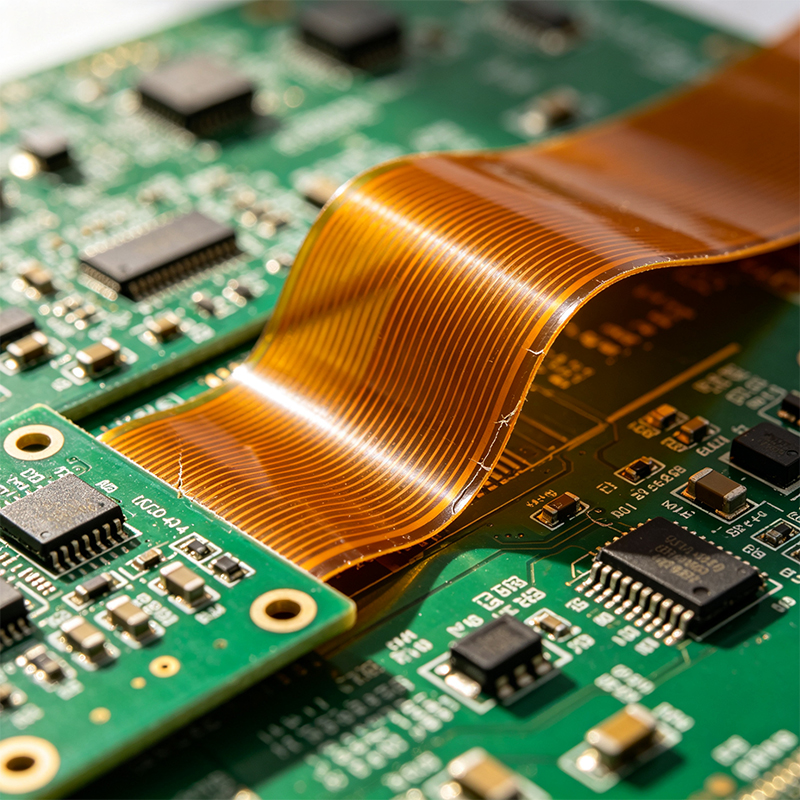
A flex‑rigid PCB is a hybrid circuit board that contains both rigid sections (usually FR4 fiberglass) and flexible sections (polyimide film) permanently laminated together. The flexible sections allow the board to bend or fold, while the rigid sections provide stable mounting for components, connectors, and heavy parts.
Think of it as a rigid board with “living hinges” built in. Instead of connecting two rigid boards with a cable and two connectors, you make one continuous board that has a flexible middle section.
Why Would You Choose a Flex‑Rigid PCB?
There are four big advantages:
Eliminate connectors – Every connector is a potential failure point. A flex‑rigid board replaces two connectors and a cable with a single, solid circuit. That’s fewer parts to source, fewer assembly steps, and fewer things that can break.
Save space – Connectors and cables take up volume. A flex‑rigid tail can be thinner and fit into tighter spaces, especially when the board needs to fold (like in a laptop hinge or a foldable phone).
Improve reliability – No loose wires, no corroded connector pins, no intermittent connections. The flexible tail is part of the board, so it won’t wiggle loose.
Simplify assembly – Instead of plugging in two connectors, you just place the whole flex‑rigid board onto the assembly line. Fewer steps = lower cost and fewer errors.
Where Are Flex‑Rigid PCBs Used?
You’ve probably used dozens of products with flex‑rigid boards without knowing it:
Laptops and tablets – The hinge area that connects the keyboard section to the screen often uses a flex‑rigid board. The rigid parts hold the processor and ports; the flexible tail bends through the hinge.
Foldable smartphones – The main board is split into two rigid sections (one for each side of the fold) connected by a multi‑layer flex‑rigid tail that survives thousands of folds.
Wearables – Smartwatches and fitness trackers use flex‑rigid boards to wrap around the wrist while keeping the main processor on a rigid section.
Medical devices – Implantable sensors and endoscope cameras need tiny, reliable interconnects. Flex‑rigid eliminates connector failure points.
Aerospace and defense – Satellites and avionics use flex‑rigid to save weight and eliminate wiring harnesses, which are heavy and prone to vibration damage.
Industrial controls – Robotics and factory automation often require boards that can move with robot arms or fit into odd-shaped enclosures.
Automotive – Dashboard clusters, steering wheel controls, and battery management systems use flex‑rigid for space‑saving connections.
Flex‑Rigid vs. Separate Rigid + Flex + Connectors – A Comparison
| Feature | Flex‑Rigid (Single Board) | Rigid Board + FPC Cable + 2 Connectors |
|---|---|---|
| Assembly steps | One board placement | Three separate parts (two boards + cable) |
| Connector count | Zero | Two (potential failure points) |
| Space | Very thin through hinge | Connectors add thickness |
| Reliability | Excellent (no moving parts) | Good, but connectors can fail |
| Cost for small volume | Higher (custom tooling) | Lower (standard parts) |
| Cost for high volume | Lower (saved assembly) | Higher (more parts and labor) |
| Design complexity | Higher | Lower |
How Is a Flex‑Rigid PCB Made?
The manufacturing process is more complex than a standard rigid board. Here’s the simplified version:
Prepare flexible cores – Polyimide flex layers (with copper traces) are fabricated separately.
Prepare rigid cores – FR4 rigid layers are fabricated.
Lamination – The flex and rigid layers are stacked and laminated together under heat and pressure. The flexible areas are protected with release sheets so they don’t bond to the rigid material.
Drilling and plating – Holes are drilled and plated, but only in the rigid areas (drilling through the flex would crack it).
Outer layer patterning – Outer copper layers are etched, covering both rigid and flex areas as needed.
Coverlay and solder mask – Flex areas get a polyimide coverlay (flexible solder mask). Rigid areas get standard epoxy solder mask.
Surface finish – ENIG (gold) or other finish is applied.
Routing – The board is cut out, including the shape of the flexible tails. Flex areas are often laser‑cut for precision.
Design Rules for Flex‑Rigid PCBs
Designing a flex‑rigid board is not like designing a rigid board. Here are the key rules:
Transition zone – The area where the rigid section meets the flex tail must be carefully designed. Traces should not change direction abruptly. Use teardrops where traces enter the flex area.
Keep vias out of flex area – Vias (plated holes) are only allowed in rigid sections. A via in the flex area will crack when the board bends.
Bend radius – The flex tail has a minimum bend radius (usually 5–10 times the flex thickness). Don’t try to bend it tighter.
Stiffeners – Add a polyimide or FR4 stiffener under any component or connector on the flex tail. Without it, the flex would flop around and break the solder joints.
Avoid sharp corners – The outline of the flex tail should have rounded corners, not sharp 90° angles. Sharp corners create stress points.
Trace routing in flex area – Traces should run perpendicular to the bend axis (across the bend, not parallel). Use staggered traces for multi‑layer flex to reduce stress.
Coverlay relief – The polyimide coverlay should be removed from areas that need to be soldered (like pads or vias in rigid sections). Leave it on flex traces.
What About HDI Flex‑Rigid?
Yes, you can combine flex‑rigid with HDI (high‑density interconnect) technology. That means microvias, fine traces (0.075mm or less), and high‑layer‑count rigid sections connected by flexible tails. These boards are used in the most advanced foldable phones and medical imaging devices.
Common Mistakes When Using Flex‑Rigid
Bending the flex tail after assembly – The board is designed to bend at the factory for installation, but repeated bending in the field may require dynamic flex design. Know the difference.
Placing heavy components on the flex tail – Even with a stiffener, heavy components (like large connectors or batteries) belong on rigid sections.
Forgetting strain relief – If the flex tail exits a housing, add a clamp or adhesive to prevent pulling.
Ignoring material stackup symmetry – An asymmetrical stackup can cause the board to curl or twist after lamination.
Flex‑Rigid vs. Rigid‑Flex – Same Thing
Just a note: “flex‑rigid” and “rigid‑flex” mean the same thing. Some manufacturers use one term, some the other. Both refer to a single board with both rigid and flexible sections.
Real‑World Example: A Foldable Drone Arm
A drone manufacturer needed a circuit that could run along a folding arm. The arm had a hinge in the middle. They tried using two rigid boards connected by a flat cable. The cable was bulky, and the connectors failed after a few hundred folds. We designed a flex‑rigid board: a rigid section at each end (for the motor and the controller), connected by a flexible tail that bent exactly at the hinge. The board weighed less, had no connectors, and survived over 10,000 folds.
What We Offer (Briefly)
We’re a custom circuit board manufacturer specializing in flexible PCBs, rigid‑flex boards, HDI high‑frequency boards, and PCBA. We design and manufacture flex‑rigid boards for any application – from simple two‑layer designs to complex multi‑layer HDI rigid‑flex with impedance control. We also offer full assembly (PCBA) and testing, so you receive ready‑to‑install boards.
Final Answer – What Is a PCB Flex‑Rigid?
A PCB flex‑rigid (rigid‑flex) is a single circuit board that combines rigid FR4 sections for components and flexible polyimide tails for bending. It eliminates connectors and cables, saving space, reducing weight, and improving reliability. Flex‑rigid boards are used in laptops, foldable phones, wearables, medical devices, aerospace, automotive, and industrial equipment.
Next time you see a laptop hinge or a foldable phone, you’re probably looking at a flex‑rigid PCB – the board that bends without breaking.

Kaboer manufacturing PCBs since 2009. Professional technology and high-precision Printed Circuit Boards involved in Medical, IOT, UAV, Aviation, Automotive, Aerospace, Industrial Control, Artificial Intelligence, Consumer Electronics etc..


 English



 Wechat
 +86 13670210335
 +86 13670210335
 E-mail