Date: 2025-07-11
Automotive electronics printed circuit boards (PCBs) play a vital role in the functionality of today’s advanced vehicles. From controlling engine systems and infotainment displays to managing safety features and autonomous driving capabilities, these PCBs require careful design and manufacturing processes to ensure optimal performance and reliability. In this article, we’ll delve into the complex journey of automotive electronics PCBs, exploring the key steps involved from the initial design stage all the way to manufacturing.
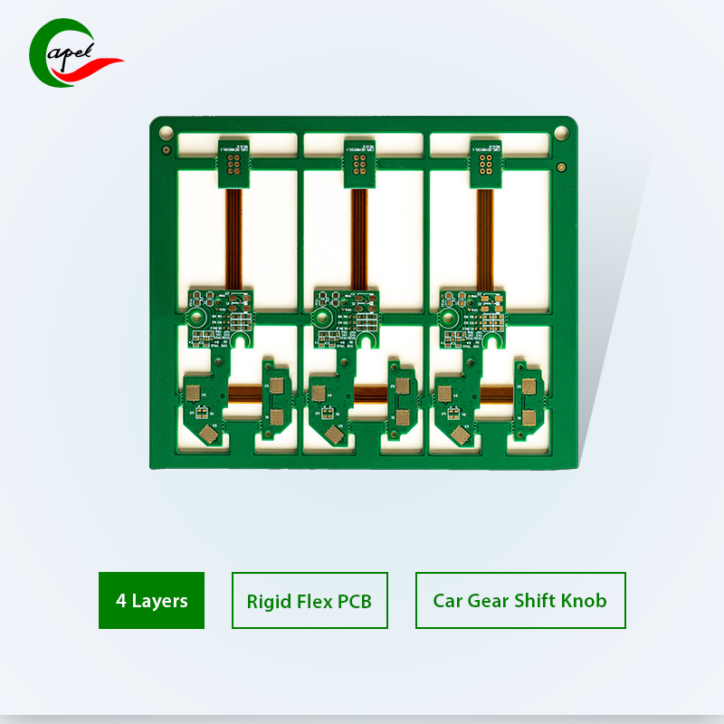
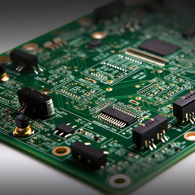
Automotive electronics PCB or printed circuit board is an important part of modern cars. They are responsible for providing electrical connections and support for various electronic systems in the car, such as engine control units, infotainment systems, sensors, etc.A key aspect of automotive electronics PCBs is their ability to withstand the harsh automotive environment. Vehicles are subject to extreme temperature changes, vibration and electrical noise. Therefore, these PCBs need to be highly durable and reliable to ensure optimal performance and safety. Automotive electronics PCBs are often designed using specialized software that allows engineers to create layouts that meet the specific requirements of the automotive industry. These requirements include factors such as size, weight, power consumption, and electrical compatibility with other components. The manufacturing process of automotive electronics PCBs involves multiple steps. The PCB layout is designed first and thoroughly simulated and tested to ensure the design meets the required specifications. The design is then transferred to the physical PCB using techniques such as etching or depositing conductive material onto the PCB substrate. Given the complexity of automotive electronic PCBs, additional components such as resistors, capacitors, and integrated circuits are usually mounted on the PCB to complete the electronic circuit. These components are typically surface mounted to the PCB using automated placement machines. Special attention is paid to the welding process to ensure proper connection and durability. Given the importance of automotive electronic systems, quality control is crucial in the automotive industry. Therefore, automotive electronic PCBs undergo rigorous testing and inspection to ensure that they meet the required standards. This includes electrical testing, thermal cycling, vibration testing and environmental testing to ensure PCB reliability and durability under a variety of conditions.
The automotive electronics PCB design process involves several critical steps to ensure the reliability, functionality, and performance of the final product.
2.1 Scheme design: The first step in the design process is schematic design. In this step, engineers define the electrical connections between individual components based on the PCB’s required functionality. This involves creating a schematic diagram that represents the PCB circuit, including connections, components, and their interrelationships. During this phase, engineers consider factors such as power requirements, signal paths, and compatibility with other systems in the vehicle.
2.2 PCB layout design: Once the schematic is finalized, the design moves into the PCB layout design phase. In this step, engineers convert the schematic into the physical layout of the PCB. This includes determining the size, shape, and location of components on the circuit board, as well as the routing of electrical traces. Layout design must consider factors such as signal integrity, thermal management, electromagnetic interference (EMI), and manufacturability. Special attention is paid to component placement to optimize signal flow and minimize noise.
2.3 Component selection and placement: After the initial PCB layout is completed, engineers continue with component selection and placement. This involves selecting appropriate components based on requirements such as performance, power consumption, availability and cost. Factors such as automotive-grade components, temperature range and vibration tolerance are critical in the selection process. The components are then placed on the PCB according to their respective footprints and positions determined during the layout design stage. Proper placement and orientation of components is critical to ensuring efficient assembly and optimal signal flow.
2.4 Signal integrity analysis: Signal integrity analysis is an important step in automotive electronics PCB design. It involves evaluating the quality and reliability of signals as they propagate through a PCB. This analysis helps identify potential problems such as signal attenuation, crosstalk, reflections, and noise interference. A variety of simulation and analysis tools are used to verify the design and optimize layout to ensure signal integrity. Designers focus on factors such as trace length, impedance matching, power integrity, and controlled impedance routing to ensure accurate and noise-free signal transmission.
Signal integrity analysis also takes into account the high-speed signals and critical bus interfaces present in automotive electronic systems. As advanced technologies such as Ethernet, CAN and FlexRay are increasingly used in vehicles, maintaining signal integrity becomes more challenging and important.
3.1 Material selection: Automotive electronics PCB material selection is critical to ensuring durability, reliability and performance. The materials used must be able to withstand the harsh environmental conditions encountered in automotive applications, including temperature changes, vibration, moisture and chemical exposure. Commonly used materials for automotive electronic PCBs include FR-4 (Flame Retardant-4) epoxy-based laminate, which has good electrical insulation, mechanical strength and excellent heat resistance. High-temperature laminates such as polyimide are also used in applications requiring extreme temperature flexibility. Material selection should also consider the requirements of the application circuit, such as high-speed signals or power electronics.
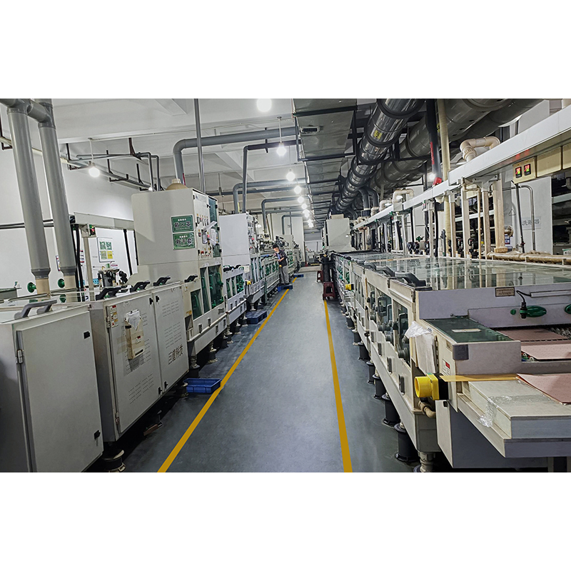
3.2 PCB manufacturing technology: PCB manufacturing technology involves multiple processes that transform designs into physical printed circuit boards. The manufacturing process typically includes the following steps:
a) Design Transfer: The PCB design is transferred to a dedicated software that generates the artwork files required for manufacturing.
b) Panelization: Combining multiple PCB designs into one panel to optimize manufacturing efficiency.
c) Imaging: Coat a layer of photosensitive material on the panel, and use the artwork file to expose the required circuit pattern on the coated panel.
d) Etching: Chemically etching the exposed areas of the panel to remove unwanted copper, leaving the desired circuit traces.
e) Drilling: Drilling holes in the panel to accommodate component leads and vias for interconnection between different layers of the PCB.
f) Electroplating: A thin layer of copper is electroplated on the panel to enhance the conductivity of the circuit traces and provide a smooth surface for subsequent processes.
g) Solder Mask Application: Apply a layer of solder mask to protect the copper traces from oxidation and provide insulation between adjacent traces. Solder mask also helps provide clear visual distinction between different components and traces.
h) Screen printing: Use the screen printing process to print component names, logos and other necessary information onto the PCB.
3.3 Prepare the copper layer: Before creating the application circuit, the copper layers on the PCB need to be prepared. This involves cleaning the copper surface to remove any dirt, oxides or contaminants. The cleaning process improves the adhesion of photosensitive materials used in the imaging process. A variety of cleaning methods can be used, including mechanical scrubbing, chemical cleaning, and plasma cleaning.
3.4 Application circuit: Once the copper layers are prepared, the application circuit can be created on the PCB. This involves using an imaging process to transfer the desired circuit pattern onto the PCB. The artwork file generated by the PCB design is used as a reference to expose the photosensitive material on the PCB to UV light. This process hardens the exposed areas, forming the required circuit traces and pads.
3.5 PCB etching and drilling: After creating the application circuit, use a chemical solution to etch away the excess copper. The photosensitive material acts as a mask, protecting the required circuit traces from etching. Next comes the drilling process of making holes for component leads and vias in the PCB. The holes are drilled using precision tools and their locations are determined based on the PCB design.
3.6 Plating and solder mask application: After the etching and drilling process is complete, the PCB is plated to enhance the conductivity of the circuit traces. Plate a thin layer of copper on the exposed copper surface. This plating process helps ensure reliable electrical connections and increases PCB durability. After plating, a layer of solder mask is applied to the PCB. The solder mask provides insulation and protects the copper traces from oxidation. It is usually applied by screen printing, and the area where the components are placed is left open for soldering.
3.7 PCB testing and inspection: The final step in the manufacturing process is PCB testing and inspection. This involves checking the functionality and quality of the PCB. Various tests such as continuity testing, insulation resistance testing, and electrical performance testing are performed to ensure that the PCB meets the required specifications. A visual inspection is also performed to check for any defects such as shorts, opens, misalignments, or component placement defects.
The automotive electronics PCB manufacturing process involves a series of steps from material selection to testing and inspection. Each step plays a critical role in ensuring the reliability, functionality and performance of the final PCB. Manufacturers must adhere to industry standards and best practices to ensure PCBs meet the stringent requirements of automotive applications.
4.1 Heat dissipation and thermal management: In automobiles, PCBs are affected by high temperature conditions due to engine heat and the surrounding environment. Therefore, heat dissipation and thermal management are key considerations in automotive PCB design. Heat-generating components such as power electronics, microcontrollers, and sensors must be strategically placed on the PCB to minimize heat concentration. Heat sinks and vents are available for efficient heat dissipation. Additionally, proper airflow and cooling mechanisms should be incorporated into automotive designs to prevent excessive heat build-up and ensure PCB reliability and longevity.
4.2 Vibration and shock resistance: Cars operate under various road conditions and are subject to vibrations and shocks caused by bumps, potholes and rough terrain. These vibrations and shocks can affect PCB durability and reliability. To ensure resistance to vibration and shock, PCBs used in automobiles should be mechanically strong and securely mounted. Design techniques such as using additional solder joints, reinforcing the PCB with epoxy or reinforcement materials, and carefully selecting vibration-resistant components and connectors can help mitigate the negative effects of vibration and shock.
4.3 Electromagnetic compatibility (EMC): Electromagnetic interference (EMI) and radio frequency interference (RFI) can adversely affect the functionality of automotive electronic equipment. The close contact of various components in the car will produce electromagnetic fields that interfere with each other. To ensure EMC, PCB design must include appropriate shielding, grounding, and filtering techniques to minimize emissions and susceptibility to electromagnetic signals. Shielding cans, conductive spacers, and proper PCB layout techniques (such as separating sensitive analog and digital traces) can help reduce the effects of EMI and RFI and ensure proper operation of automotive electronics.
4.4 Safety and reliability standards: Automotive electronics must adhere to strict safety and reliability standards to ensure the safety of passengers and the overall functionality of the vehicle. These standards include ISO 26262 for functional safety, which defines the safety requirements for road vehicles, and various national and international standards for electrical safety and environmental considerations (such as IEC 60068 for environmental testing). PCB manufacturers must understand and adhere to these standards when designing and manufacturing automotive PCBs. In addition, reliability testing such as temperature cycling, vibration testing, and accelerated aging should be performed to ensure that the PCB meets the required reliability levels for automotive applications.
Due to the high temperature conditions of the automotive environment, heat dissipation and thermal management are critical. Vibration and shock resistance are important to ensure the PCB can withstand harsh road conditions. Electromagnetic compatibility is critical to minimizing interference between various automotive electronic devices. Additionally, adhering to safety and reliability standards is critical to ensuring the safety and proper functioning of your vehicle. By solving these problems, PCB manufacturers can produce high-quality PCBs that meet the specific requirements of the automotive industry.
Automotive electronics PCB assembly and integration involves various stages including component procurement, surface mount technology assembly, automated and manual assembly methods, and quality control and testing. Each stage helps produce high-quality, reliable PCBs that meet the stringent requirements of automotive applications. Manufacturers must follow strict processes and quality standards to ensure the performance and longevity of these electronic components in vehicles.
5.1 Component procurement: Parts procurement is a critical step in the automotive electronics PCB assembly process. The procurement team works closely with suppliers to source and purchase the required components. Selected components must meet specified requirements for performance, reliability, and compatibility with automotive applications. The procurement process includes identifying reliable suppliers, comparing prices and delivery times, and ensuring components are genuine and meet necessary quality standards. Procurement teams also consider factors such as obsolescence management to ensure component availability throughout the product lifecycle.
5.2 Surface Mount Technology (SMT): Surface mount technology (SMT) is the preferred method for assembling automotive electronics PCBs due to its efficiency, precision, and compatibility with miniaturized components. SMT involves placing components directly onto the PCB surface, eliminating the need for leads or pins. SMT components include small, lightweight devices such as resistors, capacitors, integrated circuits, and microcontrollers. These components are placed on the PCB using an automated placement machine. The machine precisely positions components on the solder paste on the PCB, ensuring precise alignment and reducing the chance of errors. The SMT process offers several benefits, including increased component density, improved manufacturing efficiency, and enhanced electrical performance. In addition, SMT enables automated inspection and testing, enabling fast and reliable production.
5.3 Automatic and manual assembly: Assembly of automotive electronics PCBs can be accomplished by automated and manual methods, depending on the complexity of the board and the specific requirements of the application. Automated assembly involves the use of advanced machinery to assemble PCBs quickly and accurately. Automated machines, such as chip mounters, solder paste printers, and reflow ovens, are used for component placement, solder paste application, and reflow soldering. Automated assembly is highly efficient, reducing production time and minimizing errors. Manual assembly, on the other hand, is typically used for low-volume production or when certain components are not suitable for automated assembly. Skilled technicians use specialized tools and equipment to carefully place components on the PCB. Manual assembly allows greater flexibility and customization than automated assembly, but is slower and more prone to human error.
5.4 Quality Control and Testing: Quality control and testing are critical steps in automotive electronics PCB assembly and integration. These processes help ensure that the final product meets the required quality standards and functionality. Quality control begins with inspecting incoming components to verify their authenticity and quality. During the assembly process, inspections are conducted at various stages to identify and correct any defects or issues. Visual inspection, automated optical inspection (AOI) and X-ray inspection are often used to detect possible defects such as solder bridges, component misalignment or open connections.
After assembly, the PCB needs to be functionally tested to verify its performance. Testing procedures may include power-on testing, functional testing, in-circuit testing, and environmental testing to verify the functionality, electrical characteristics, and reliability of the PCB.
Quality control and testing also involves traceability, where each PCB is tagged or marked with a unique identifier to track its production history and ensure accountability. This enables manufacturers to identify and correct any issues and provides valuable data for continuous improvement.
6.1 Miniaturization and increased complexity: One of the important trends in automotive electronics PCBs is the continuous push for miniaturization and complexity. As vehicles become more advanced and equipped with various electronic systems, the demand for smaller and denser PCBs continues to increase. This miniaturization poses challenges in component placement, routing, thermal dissipation, and reliability. PCB designers and manufacturers must find innovative solutions to accommodate shrinking form factors while maintaining PCB performance and durability.
6.2 Integration of advanced technologies: The automotive industry is witnessing rapid advancements in technology, including the integration of advanced technologies into vehicles. PCBs play a key role in enabling these technologies, such as advanced driver assistance systems (ADAS), electric vehicle systems, connectivity solutions and autonomous driving features. These advanced technologies require PCBs that can support higher speeds, handle complex data processing, and ensure reliable communication between various components and systems. Designing and manufacturing PCBs that meet these requirements is a major challenge for the industry.
6.3 The manufacturing process needs to be strengthened: As the demand for automotive electronics PCBs continues to grow, manufacturers are faced with the challenge of enhancing manufacturing processes to meet higher production volumes while maintaining high quality standards. Streamlining production processes, improving efficiency, shortening cycle times and minimizing defects are areas where manufacturers need to focus their efforts. The use of advanced manufacturing technologies, such as automated assembly, robotics and advanced inspection systems, helps improve the efficiency and accuracy of the production process. Adopting Industry 4.0 concepts such as the Internet of Things (IoT) and data analytics can provide valuable insights into process optimization and predictive maintenance, thereby increasing productivity and output.
Shenzhen Capel Technology Co., Ltd. established a circuit board factory in 2009 and began to develop and manufacture flexible circuit boards, hybrid boards, and rigid boards. Over the past 15 years, we have successfully completed tens of thousands of automotive circuit board projects for customers, accumulated rich experience in the automotive industry, and provided customers with safe and reliable solutions. Capel’s professional engineering and R&D teams are the experts you can trust!
In summary, the automotive electronics PCB manufacturing process is a complex and meticulous task that requires close collaboration between engineers, designers, and manufacturers. The stringent requirements of the automotive industry require high-quality, reliable and safe PCBs. As technology continues to advance, automotive electronics PCBs will need to meet the growing demand for more complex and sophisticated functions. To stay ahead of this rapidly evolving field, PCB manufacturers must keep up with the latest trends. They need to invest in advanced manufacturing processes and equipment to ensure the production of top-notch PCBs. Employing high-quality practices not only enhances the driving experience, but also prioritizes safety and precision.
Capel manufacturing PCBs since 2009. Professional technology and high-precision Printed Circuit Boards involved in Medical, IOT, UAV, Aviation, Automotive, Aerospace, Industrial Control, Artificial Intelligence, Consumer Electronics etc..