PCB Process Capability
| No. | Project | Technical indicators |
| 1 | Layer | 1-60(layer) |
| 2 | Maximum processing area | 545 x 622 mm |
| 3 | Minimumboardthickness | 4(layer)0.40mm |
| 6(layer) 0.60mm |
| 8(layer) 0.8mm |
| 10(layer)1.0mm |
| 4 | Minimum line width | 0.0762mm |
| 5 | Minimum spacing | 0.0762mm |
| 6 | Minimum mechanical aperture | 0.15mm |
| 7 | Hole wall copper thickness | 0.015mm |
| 8 | Metallized aperture tolerance | ±0.05mm |
| 9 | Non-metallized aperture tolerance | ±0.025mm |
| 10 | Hole tolerance | ±0.05mm |
| 11 | Dimensional tolerance | ±0.076mm |
| 12 | Minimum solder bridge | 0.08mm |
| 13 | Insulation resistance | 1E+12Ω(normal) |
| 14 | Plate thickness ratio | 1:10 |
| 15 | Thermal shock | 288 ℃(4 times in 10 seconds) |
| 16 | Distorted and bent | ≤0.7% |
| 17 | Anti-electricity strength | >1.3KV/mm |
| 18 | Anti-stripping strength | 1.4N/mm |
| 19 | Solder resist hardness | ≥6H |
| 20 | Flame retardancy | 94V-0 |
| 21 | Impedance control | ±5% |
We Do HDI Circuit Board With 15 Years' Experience With Our Professionalism
4 layer Flex-Rigid Boards
Testing And Inspection Equipment
Our HDI Circuit Board Service
. Provide technical support Pre-sales and after-sales;
. Custom up to 40 layers, 1-2days Quick turn reliable prototyping, Component procurement, SMT Assembly;
. Caters to both Medical Device, Industrial Control, Automotive, Aviation, Consumer Electronics, IOT, UAV, Communications etc.
. Our teams of engineers and researchers are dedicated to fulfilling your requirements with precision and professionalism.
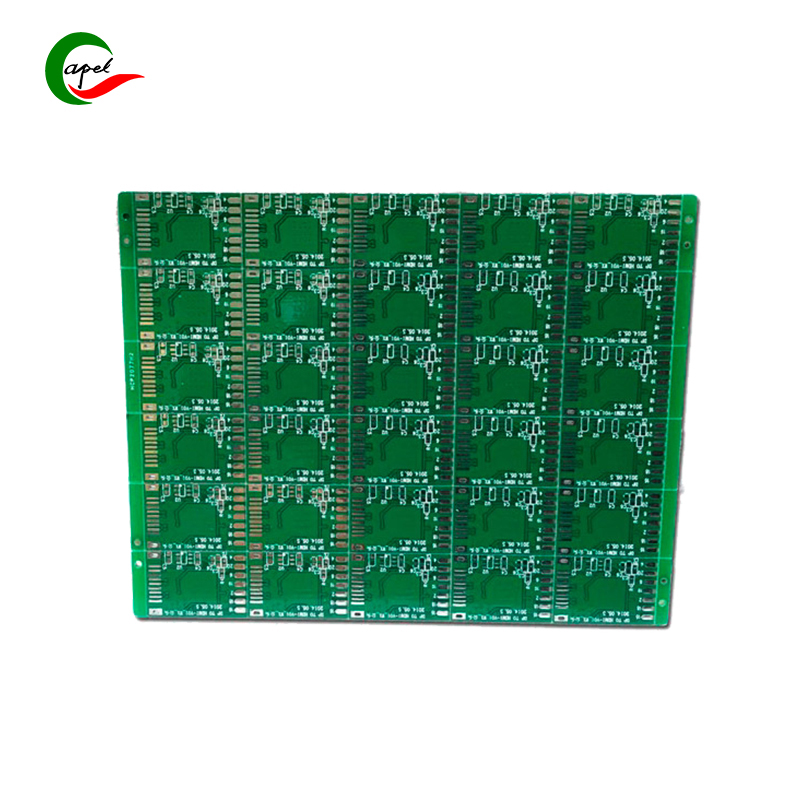
Single-Layer Fr4 PCB Board Applicated In UAV
1. Size and layout optimization: Since a single-layer FR4 PCB provides limited space for components and traces, the size and layout of the board must be optimized to accommodate all necessary components and traces. This can require careful component placement and strategic routing to minimize signal interference and maximize efficiency.
2. Power distribution and voltage regulation: Reasonable power distribution and voltage regulation is the key to the stable and reliable operation of UAVs. A single-layer FR4 PCB should be designed to house the power circuitry, including voltage regulators, filters, and decoupling capacitors, to ensure consistent power to all components.
3. Signal integrity considerations: UAVs often require precise communication and control, so signal integrity is critical.Single-layer FR4 PCBs may be more susceptible to signal interference and noise than multi-layer boards. Design considerations such as trace impedance control, proper ground plane design, and alignment of sensitive circuits should be considered to maintain signal integrity.

4. Component placement and vibration resistance: UAVs will be subject to vibration and shock during operation, so the vibration resistance should be considered when placing components on a single-layer FR4 PCB. Mounting components securely, using vibration-damping materials, and implementing proper soldering techniques are critical to ensuring PCB longevity and reliability.
5. Thermal management: UAVs often generate heat due to motors, electronic components, and power supplies. Effective thermal management is necessary to prevent overheating and component failure. When designing a single-layer FR4 PCB, consideration should be given to allow enough space for heat sinks, thermal vias, and proper airflow for effective heat dissipation.
6. Environmental considerations: Drones can operate in a variety of environmental conditions, including high humidity, temperature changes, and exposure to dust and moisture. Single-layer FR4 PCBs should be designed with proper conformal coating or encapsulation to protect against environmental elements and ensure long-term reliability.
Single-Layer Fr4 PCB Board FAQ
1. What is FR4 PCB?
FR4 refers to a flame retardant fiberglass epoxy laminate used in PCB (printed circuit board) manufacturing.
FR4 PCB is widely used for its excellent electrical insulation, mechanical strength and flame retardancy.
2. What is a single-layer FR4 PCB?
A single layer FR4 PCB is a PCB design with only one layer of copper traces and components mounted on one side of the board.
Compared with multi-layer PCB, its design is simpler and simpler.
3. What are the advantages of single-layer FR4 PCB?
- Cost-effective: Single-layer FR4 PCBs are generally more affordable compared to multi-layer boards.
- Easier Manufacture: They are easier to manufacture as they require less complex processes and fewer layers.
- Suitable for simple designs: A single layer PCB is sufficient for simple applications that do not require significant circuit complexity or miniaturization.
4. What are the limitations of a single layer FR4 PCB?
- Limited routing options: With only one layer of copper traces, routing of complex circuits or designs with high component density can be challenging.
- More susceptible to noise and interference: Single-layer PCBs can have more signal integrity issues due to lack of ground plane and isolation between different signal traces.
- Larger board size: Since all traces, components, and connections are on one side of the board, single-layer FR4 PCBs tend to have a larger size than multilayer boards with similar functionality.
5. What types of applications are suitable for single-layer FR4 PCB?
- Simple Electronics: Single-layer FR4 PCBs are often used for basic electronic circuits such as power supplies, LED lighting, and low-density control systems.
- Prototyping and Hobbyist Projects: Single-layer FR4 PCBs are popular among hobbyists due to their affordability and are used in the initial prototyping stage before expanding to multi-layer designs.
- Educational and Learning Purposes: Single layer PCBs are often used in educational settings to teach basic concepts of electronics and circuit design.
6. Are there any design considerations for a single layer FR4 PCB?
- Component Placement: Efficient component placement is critical to optimize routing and minimize signal interference on a single-layer PCB.
- Trace Routing: Trace routing with careful consideration of signal integrity, avoiding cross-signals, and minimizing trace length helps maintain reliable performance.
- Grounding and Power Distribution: Adequate grounding and power distribution are critical to avoid noise problems and ensure proper circuit operation.


 English
 Single-Sided Fr4 PCB Manufacturer Rogers Pcb


 Wechat
 +86 13670210335
 +86 13670210335
 E-mail