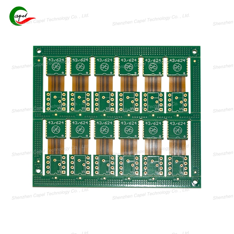
Rigid-flex PCBs are a hybrid solution for complex devices—but their production is often slower than standard PCBs, thanks to their mix of rigid and flexible layers, precise transitions, and strict quality checks. For manufacturers racing to launch products (like foldable phones or medical wearables), every extra day in production can mean lost market share. We asked PCB engineering experts to share their proven strategies to cut lead times without sacrificing quality. Here’s what they had to say.
The Problem: A common delay happens when design flaws (e.g., incorrect flex zone radius, misaligned layers) are caught mid-production—forcing teams to redo photomasks, re-etch traces, or even restart the lamination process. One expert we spoke to noted this can add 7–10 days to a typical 3-week cycle.
Expert Fix:
-
Conduct a cross-functional design review before production begins. Include PCB designers, manufacturing engineers, and quality inspectors to spot issues early. For example, an engineer might flag that a flex zone’s 0.5mm radius is too tight (minimum should be 1mm for the chosen material)—fixing this in the design phase takes hours, not days.
-
Use rigid-flex design software (e.g., Altium Designer, Cadence Allegro) with built-in rule checks. These tools auto-detect mistakes like overlapping traces in flex zones or insufficient buffer space between rigid and flex sections.
The Problem: Sourcing custom materials (e.g., rare polyimide films for flex zones) or non-standard components (specialty connectors) can cause weeks of delays—suppliers often need time to manufacture or ship these items.
Expert Fix:
-
Create a pre-approved material list (PAML) for rigid-flex PCBs. Stick to widely available materials like standard PI films (12.5–50μm) or high-Tg FR-4 for rigid sections—suppliers keep these in stock, so lead times drop from 2 weeks to 2–3 days.
-
Use standardized component footprints (e.g., 0402 SMD resistors instead of custom sizes). This avoids waiting for custom components and speeds up assembly, as pick-and-place machines are pre-calibrated for standard parts.
The Problem: Laminating rigid and flex layers (a critical step) is often slow—misalignment here can ruin the board, so manufacturers tend to take extra time. Transition zones (where rigid meets flex) also require careful etching, which adds hours.
Expert Fix:
-
Invest in automated lamination equipment with optical alignment. Unlike manual lamination (which takes 2–3 hours per batch and risks misalignment), these machines align layers in minutes with ±0.05mm precision—cutting lamination time by 50%.
-
Use pre-cut transition zone templates. Instead of etching transition zones from scratch for each design, create reusable templates for common flex-rigid ratios (e.g., 3mm buffer between rigid and flex). This shaves 4–6 hours off the etching process.
The Problem: Traditional QC for rigid-flex PCBs is labor-intensive—inspectors manually check flex zone cracks, layer adhesion, and impedance with microscopes. This can take 1–2 days for a large batch.
Expert Fix:
-
Adopt automated optical inspection (AOI) for post-etch and post-lamination checks. AOI machines scan boards in seconds, flagging issues like thin traces or pinholes in cover layers that human eyes might miss. One expert reported AOI cut QC time by 70%.
-
Use in-line bend testers for flex zones. Instead of testing a small sample batch after production, integrate testers into the assembly line to check flexibility in real time. This catches issues early and eliminates the need for re-testing later.
The Problem: Waiting for suppliers to deliver raw materials (e.g., copper foil, adhesive) or tooling (e.g., photomasks) is a top delay. International suppliers can add 2–3 weeks of shipping time.
Expert Fix:
Founded in 2009, our company has deep roots in the production of various circuit boards. We are dedicated to laying a solid electronic foundation and providing key support for the development of diverse industries.
Whether you are engaged in electronic manufacturing, smart device R&D, or any other field with circuit board needs, feel free to reach out to us via email at sales06@kbefpc.com. We look forward to addressing your inquiries, customizing solutions, and sincerely invite partners from all sectors to consult and collaborate, exploring new possibilities in the industry together.
