Date: 2025-10-13
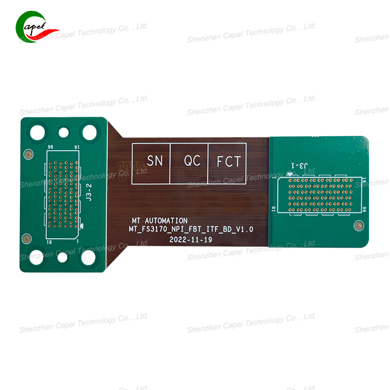
Here's a problem that keeps PCB manufacturers up at night: you're drilling metallized holes in rigid-flex boards, and suddenly the flexible areas start deforming. The holes end up misaligned, the walls look rough, and sometimes the flex layer even tears. After dealing with this issue across dozens of projects, I've developed some practical solutions that actually work.
The Support System: Giving Your Flex Material a Backbone
The single most effective trick we've discovered? Add temporary rigidity to those floppy flex regions before drilling even begins.
Choosing Your Support Material:
For thinner flex layers (≤50μm PI), we use 0.1mm aluminum foil carriers. They're cheap, readily available, and peel off cleanly after drilling.
When working with thicker flex materials (≥75μm PI), we upgrade to 0.2mm FR-4 spacers or rigid plastic sheets. The extra stiffness matters for deeper holes.
Getting the Application Right:
Start with a thorough IPA cleaning - any contamination affects adhesion
Use low-tack adhesive (we prefer 3M's low-residue options) to mount the carrier
Watch for air bubbles like a hawk - they create weak spots that defeat the purpose
Secure the entire assembly with vacuum suction on the drilling table

Drill Bit Selection: It's All About the Geometry
Using the wrong drill bit guarantees problems. We learned this the hard way when a batch of medical sensor boards failed quality control due to torn hole walls.
Our Drill Specs:
Material: Carbide-only policy (HSS doesn't maintain sharpness long enough)
Point angle: 90°-120° instead of the standard 135°-140° for FR-4
Size discipline: Match drill diameter exactly to finished hole size requirements
The smaller point angle makes a huge difference - it pierces through PI cleanly rather than pushing and stretching the material.
Dialing in the Process Parameters
You can't run flex materials with the same aggressive parameters used for rigid FR-4. Through extensive testing, we've settled on these optimized settings:
Spindle speed: 20,000-30,000 RPM (significantly lower than our 35,000-45,000 RPM for rigid boards)
Feed rate: 0.1-0.2 mm/rev (about half our typical FR-4 rate)
Depth control: Stop 0.1mm short of the rigid-flex interface
The slower feed rate is particularly important - it gives the material time to cleanly separate rather than tearing.
The Finishing Touches That Matter
How you handle the boards after drilling is just as important as the drilling process itself.
We carefully peel carriers at a 45° angle - straight-up removal can distort the freshly drilled holes. Immediate inspection under 10-20x magnification catches any issues before they affect downstream processes.
The Bottom Line
Preventing flex region deformation comes down to three key principles: proper support before drilling, optimized drill geometry, and patient process parameters. Implementing these steps has reduced our drilling-related rework by over 80% across multiple product lines. The small time investment in setup pays for itself many times over in improved yield and reliability.
related link:
Kaboer manufacturing PCBs since 2009. Professional technology and high-precision Printed Circuit Boards involved in Medical, IOT, UAV, Aviation, Automotive, Aerospace, Industrial Control, Artificial Intelligence, Consumer Electronics etc..