Date: 2025-10-20
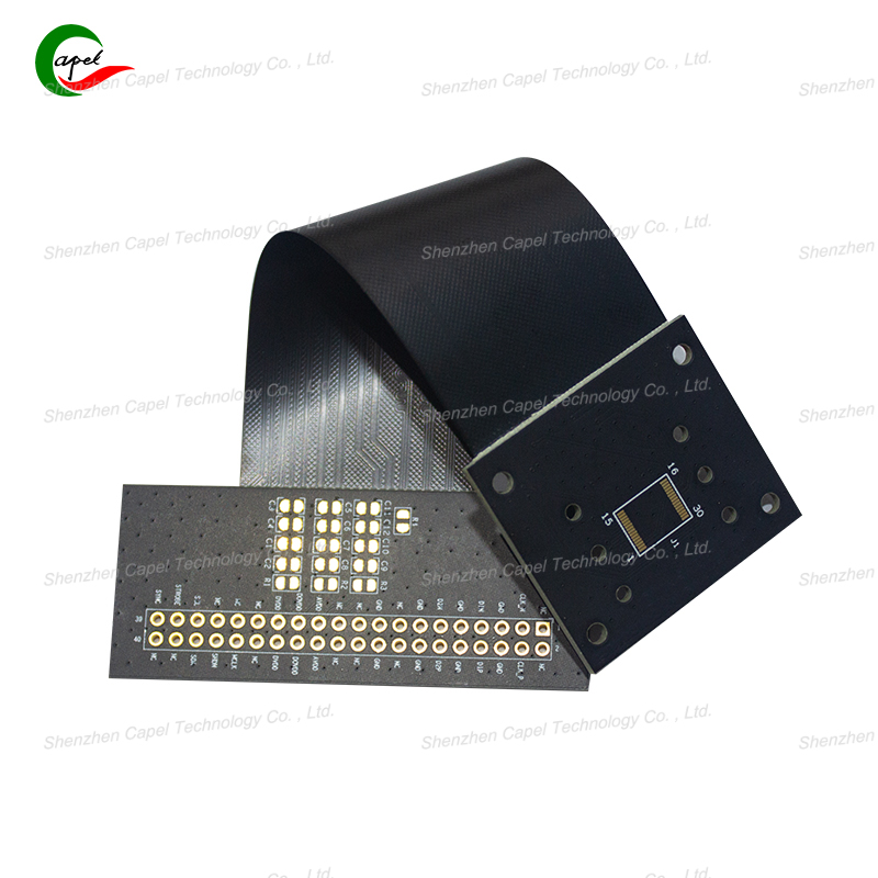
Let me tell you about our "aha" moment. We'd just received another batch of rigid-flex boards back from field testing - automotive sensor modules this time. And there it was again: that hairline crack right where the FR-4 met the polyimide. Not on every board, but enough to wreck our yield.
We'd been treating these multi-material joints like any other bond. Big mistake.
After tearing apart failed units and running countless experiments, we realized the problem wasn't the materials themselves, but what happened where they met. It was like trying to glue a brick to a rubber band - they just want to move differently.
You can't fix what you don't understand. We found four core issues:
Thermal tug-of-war: When temperatures change, your FR-4 wants to expand about 13 ppm for every degree C, while polyimide wants to expand 50 ppm. They're literally fighting each other with every power cycle.
The stiffness leap: Going from rigid to flexible creates a natural stress concentration point. Think of it like trying to bend a credit card that's glued to a piece of paper - where do you think it's going to tear?
Adhesive limitations: Most standard epoxies can't handle being the middleman in this mismatch. They either get brittle when cold or soft when hot.
Process inconsistencies: We discovered that even slight variations in lamination pressure or temperature created weak spots that would fail later.
After much trial and error, here's the approach that finally gave us reliable joints:
Material Selection - Get This Right First
We switched to LCP for high-temp apps: Liquid crystal polymer's CTE (15-20 ppm/°C) is much closer to FR-4 than standard PI. This one change reduced our thermal cycling failures by about 60%.
Stop using generic adhesives: We now use two-part acrylics specifically formulated for dissimilar materials. 3M's DP460 became our workhorse for most applications.
Balance your thickness: We keep flexible layers at about one-third to one-half the thickness of the rigid sections. This seems to create the best stress distribution.
Joint Design - This is Where the Magic Happens
Taper everything: We never use 90-degree transitions anymore. Now we taper the rigid board edge from full thickness down to about 0.2mm over a 3-5mm distance, then run the flex material 2-3mm onto this tapered area. The difference was dramatic - stress concentrations dropped by half.
Round those corners: Any sharp edge is a potential failure point. We use 0.5-1.0mm radii on all joint edges.
Reinforce smartly: A thin PI reinforcement sheet over the joint area helps, but only if you get the coverage right. We cover 1-2mm onto the rigid section and 3-4mm onto the flex. Any more and you're just moving the problem.

Process Control - Where Good Designs Actually Work
Temperature matters: We stay between 80-120°C for acrylics, 120-140°C for modified epoxies. Going over 150°C consistently caused problems with the flex materials.
Pressure needs to be just right: 0.3-0.5 MPa, applied uniformly. More pressure isn't better - we learned this the hard way after crushing a batch of delicate flex layers.
Don't rush the cure: 30-60 minutes for acrylics, 60-90 for epoxies. Anything less and you're not getting full strength.
Surface Prep - The Step Everyone Wants to Skip
I can't emphasize this enough: if you skip proper surface prep, you're building on a weak foundation. We:
Clean with isopropyl alcohol
Use oxygen plasma treatment (30 seconds at 50W) or mild acid etch
This alone improved our bond strength by 30-40%.
For really demanding applications - think robotic arms or aerospace components - we add mechanical locking:
Micro-grooves: 0.1-0.2mm deep grooves spaced 0.5mm apart on the rigid board let the adhesive form mechanical interlocks
Stitch holes: 0.3-0.4mm holes every 1-2mm along the joint create adhesive anchors
Trying to fix bad designs with process: If you have a 90-degree transition, no amount of process magic will save it
Using whatever adhesive was handy: Generic epoxies consistently failed in thermal cycling
Over-reinforcing: Making the flex area too stiff just moves the failure point
Rushing validation: We now test thoroughly - thermal cycling (-40°C to 125°C, 1000 cycles) and bend testing (10,000 cycles) are non-negotiable
What finally worked for us was treating these joints as specialized systems requiring:
Materials selected for compatibility, not just individual properties
Gradual transitions that distribute stress instead of concentrating it
Process controls that recognize these are delicate operations
Validation that proves the joints will survive in the real world
The approach isn't complicated, but it requires discipline. Get these elements right, and you can finally stop worrying about those hairline cracks.
related link:
Kaboer manufacturing PCBs since 2009. Professional technology and high-precision Printed Circuit Boards involved in Medical, IOT, UAV, Aviation, Automotive, Aerospace, Industrial Control, Artificial Intelligence, Consumer Electronics etc..