Date: 2025-11-06
Let me walk you through what's really inside those complex flexible circuit boards with four or more layers. Think of them like a carefully crafted club sandwich - multiple layers working together, each with a specific job.
The Essential Layers (What Makes It Work)
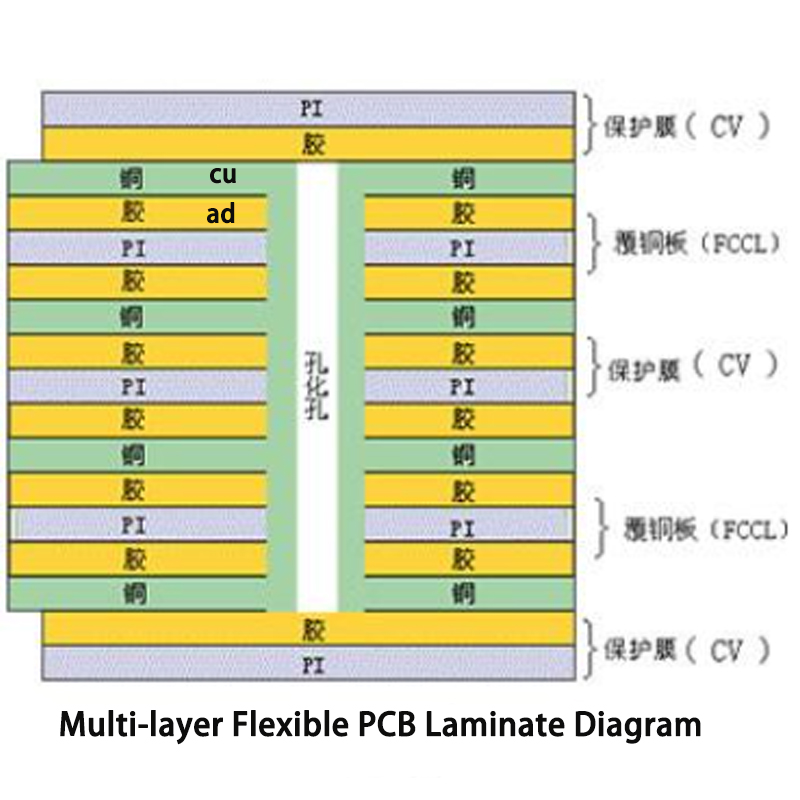
At the heart of every multi-layer flex board is the core material - usually polyimide (we call it PI). This is the flexible foundation that everything builds on. It's thin, tough, and can handle soldering heat without complaining.
Inside the stack, we have copper layers - some buried in the middle, some on the outside. The inner layers handle the main circuitry, while the outer layers are where components get mounted. We use different types of copper depending on how much bending the board needs to do.
Everything is held together with special flexible adhesive. This isn't your ordinary glue - it has to stay flexible while surviving high temperatures during manufacturing.
The whole thing gets wrapped in protective cover layers. These flexible films keep moisture, dust, and physical damage away from the delicate copper circuits.
The Smart Connections Between Layers
This is where multi-layer boards get clever. Instead of just having holes going all the way through (like in simpler boards), we use:
Blind vias - connect outer layers to specific inner layers without going all the way through
Buried vias - connect inner layers to each other, completely hidden inside the stack
Through vias - the traditional holes that go through everything (used less in flex boards)
This approach saves space and reduces stress on the flexible materials.
Extra Features You Can Add
Depending on what the board needs to do, we might add:
Stiffeners - rigid sections near connectors where components get inserted and removed frequently
Shielding - thin conductive layers that block electrical interference
Heat spreaders - extra copper or special materials to pull heat away from hot components
Labels and markings - to show where everything goes during assembly
A Real-World Example: 4-Layer Flex Board
If we could peel apart a typical 4-layer board, from top to bottom we'd find:
Protective cover
Top copper circuit layer
Flexible substrate
Second copper layer
Central core material
Third copper layer
Flexible substrate
Bottom copper circuit layer
Protective cover
All these layers are permanently bonded together into one flexible unit.
What Makes These Boards Special
You get incredible circuit density - imagine having multiple floors of wiring in the space usually taken by one. This lets us separate different types of signals (power, data, sensitive analog signals) to prevent interference.
They're still flexible, though not as bendy as single-layer boards. The more layers you add, the stiffer the board becomes. Most multi-layer flex boards can handle bending radii of 5-10mm.
The tricky part is manufacturing. Getting all those layers to align perfectly is like trying to stack ten pieces of paper and have all the edges match exactly. It requires expensive equipment and skilled operators.
When You'd Actually Need One
These aren't your everyday circuit boards. You'd use multi-layer flex when:
Space is extremely limited but you need complex circuitry
You have interference issues between different circuits
You need reliable performance in tough environments
Cost is secondary to performance and reliability
They're common in military equipment, medical devices, high-end smartphones, and aerospace applications where failure isn't an option.
The bottom line: multi-layer flex gives you the complexity of rigid boards with some flexibility, but you pay for it in cost and manufacturing complexity. They're amazing when you need them, but overkill for most applications.
Kaboer manufacturing PCBs since 2009. Professional technology and high-precision Printed Circuit Boards involved in Medical, IOT, UAV, Aviation, Automotive, Aerospace, Industrial Control, Artificial Intelligence, Consumer Electronics etc..