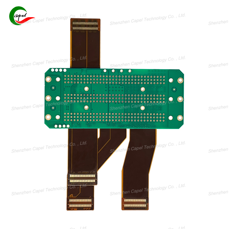
PCB design isn’t just drawing lines on a screen—it’s turning a circuit idea into something physical that works. Every designer has stared at a schematic, wondering, “How do I make this not fail?” The secret isn’t perfection; it’s following small, smart rules that avoid big mistakes. Let’s break down the steps that turn messy ideas into reliable boards.
A messy schematic is a recipe for layout disaster. An engineer once skipped organizing their schematic—they had resistors labeled “R1” to “R50” with no grouping, and power paths crisscrossing everywhere. When they moved to layout, they missed a ground connection, forcing a full redesign.
Do this instead:
-
Group components by function (e.g., “Power Supply,” “Sensor Circuit,” “Bluetooth Module”).
-
Label clearly: “R3 (Pull-Up for Button)” is better than just “R3.”
-
Add notes for tricky parts: “This op-amp needs a 0.1uF capacitor near VCC.”
A clean schematic cuts layout time by 30%—no more hunting for hidden connections.
Layout is where most designers get stuck. It’s easy to focus on fitting all components, but ignoring signal or power needs breaks the board. A hobbyist once designed a drone PCB where they squeezed a motor driver next to a GPS module—motor noise messed up the GPS signal, making the drone drift.
Key layout rules:

Ordering PCBs without checking is like baking a cake without tasting—you’ll likely waste time and money. A startup once sent a design to manufacturing without verifying footprints; their microcontroller was too big for the pad, and 100 boards were useless.
Must-do checks:
-
Run DRC (Design Rule Check) twice: Once after layout, once before sending files. DRC catches trace spacing errors, too-thin lines, or missing connections.
-
Verify footprints: Use datasheets to confirm pad sizes (e.g., “This LED needs a 2.0mm x 1.2mm pad, not 1.5mm x 1.0mm”).
-
Do a “mental test”: Imagine powering the board—does current flow smoothly? Are signals getting from sensor to microcontroller without interference?
Thinking “I’ll get it right the first time” is risky. A designer once made a smart thermostat PCB and ordered 50 units directly—only to find the LCD backlight didn’t work (they used the wrong voltage resistor). They had to reorder, delaying launch by a month.
Always prototype with 2-5 boards first. Prototyping lets you:
-
Test functionality: Does the board turn on? Do all sensors read correctly?
-
Fix small issues: A resistor value tweak or a trace width adjustment is easy on a prototype.
-
Save money: Fixing 5 boards costs $50; fixing 50 costs $500.
PCB design is a mix of logic and patience. By starting with a clean schematic, balancing layout needs, checking thoroughly, and prototyping, you’ll avoid the mistakes that make designers want to quit. It’s not about being a pro—it’s about following steps that turn your idea into a board that works, first try.
Founded in 2009, our company has deep roots in the production of various circuit boards. We are dedicated to laying a solid electronic foundation and providing key support for the development of diverse industries.
Whether you are engaged in electronic manufacturing, smart device R&D, or any other field with circuit board needs, feel free to reach out to us via email at sales06@kbefpc.com. We look forward to addressing your inquiries, customizing solutions, and sincerely invite partners from all sectors to consult and collaborate, exploring new possibilities in the industry together.
