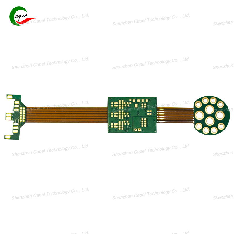
Rigid-Flex PCB Drilling: High-Precision Control Solutions
Date: 2025-09-17
Drilling might seem like the "simple part" of making rigid-flex PCBs—just poke holes to connect layers or mount components. But with rigid-flex boards, it’s anything but easy. You’re drilling through two very different materials: hard, stiff FR-4 (the rigid layers) and thin, bendable polyimide (PI, the flexible layers). Miss the mark by even 0.1mm, and you’ll ruin traces, break the flexible section, or make the board useless.
High-precision drilling isn’t about luck—it’s about controlling the process. Below’s a straightforward breakdown of why rigid-flex drilling is tricky, the key steps to keep holes accurate, and why those tiny holes matter so much.
Ordinary PCBs are all one material (like FR-4), so drilling is predictable. Rigid-flex boards throw two curveballs:
-
Mixed material resistance: FR-4 is tough and needs force to drill, while PI is soft and tears easily if the drill moves too fast. A setting that works for one will mess up the other.
-
Layer shift risk: The flexible PI layers can slide against the rigid FR-4 during drilling—even a tiny shift means holes line up wrong between layers.
-
Tiny hole demands: Rigid-flex PCBs use holes as small as 0.1mm (thinner than a human hair) to save space. A drill bit that’s even slightly dull will widen the hole or leave rough edges.
Precision starts before the drill hits the board. Follow these steps to avoid mistakes:
-
Secure the board (no sliding allowed)
Use a vacuum clamp to hold the rigid-flex stack tightly against a flat surface. The vacuum pulls all layers (FR-4 and PI) together, so they don’t shift while drilling. For extra safety, add a thin "backing plate" (like aluminum) under the board—this stops the PI from tearing when the drill exits.
-
Pick the right drill bit (sharp + sized for the job)
Use carbide drill bits (not steel)—they stay sharp longer and cut through mixed materials cleanly. Match the bit size exactly to the hole you need: a 0.1mm hole needs a 0.1mm bit (no rounding up). Replace bits after 500–1000 holes—dull bits cause burrs (rough edges) that damage traces.
-
Tweak speed and force (match the material)
Adjust the drill’s RPM (speed) and feed rate (how fast it pushes down) for each layer:
-
Rigid FR-4: Slow speed (10,000–15,000 RPM) + moderate force—this avoids cracking the FR-4.
-
Flexible PI: Fast speed (20,000–30,000 RPM) + light force—this cuts the PI cleanly without tearing.
Many modern drills have "auto-adjust" settings that switch between modes as they move through layers.
Even with prep, problems pop up. Here’s how to spot and fix them:
-
Holes off-center (layer shift)
Why it happens: Board wasn’t clamped tight enough, or PI layers slid before drilling.
Fix: Check the vacuum clamp’s seal before drilling. For thick boards, add a "stitch tape" around the edges to hold layers together.
-
Rough edges (burrs) on PI layers
Why it happens: Dull drill bit or too-slow speed.
Fix: Replace the drill bit and crank up the RPM for the PI section. After drilling, use a tiny brush with alcohol to smooth any burrs.
-
Holes too big (oversized)
Why it happens: Bit is worn or the feed rate is too high.
Fix: Use a new bit and slow the feed rate—let the bit cut, don’t force it.
Those tiny holes might seem unimportant, but they make or break the rigid-flex board:
-
Layer connection: Holes (called "vias") link rigid and flexible layers. Misaligned holes mean no signal or power between layers—dead spots in the circuit.
-
Component fit: Screws or connectors go through mounting holes. Oversized holes make parts loose; undersized holes crack the board when you try to insert components.
-
Flexible section strength: A misplaced hole near the rigid-flex transition can weaken the PI, making the board crack when bent.
Rigid-flex PCB drilling is a balancing act—managing two materials, tiny holes, and zero room for error. But with tight clamping, the right drill bits, and material-matched speed/force, you can get holes that are straight, sized perfectly, and aligned every time.
The next time you hold a rigid-flex PCB, look closely at those tiny holes. Each one is a sign of precision—proof that the board was built to bend, connect, and last. In rigid-flex design, it’s the smallest details (like a 0.1mm hole) that make the biggest difference.
related link: