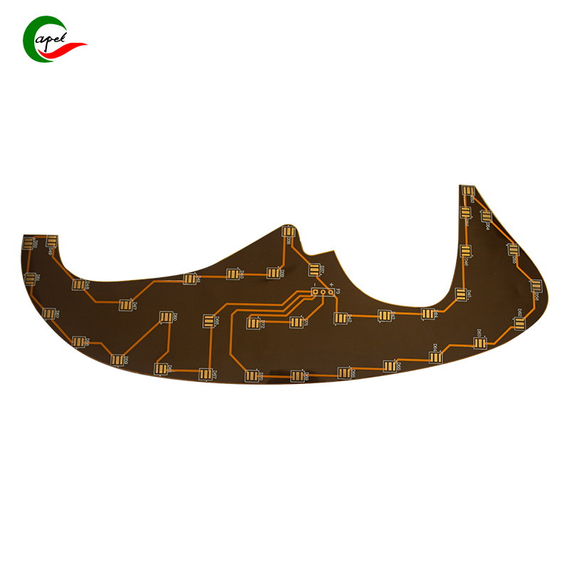
Last summer, Lena, a lead engineer at a European automaker, stared at a dead EV prototype cockpit: infotainment blacked out, climate control unresponsive. “We built a cockpit with 15-inch touchscreen, HUD, and wireless charger—but connecting them turned wiring into a rat’s nest,” she said. “Rigid PCBs didn’t fit tight spaces, and loose wires shorted out. That prototype was useless for two weeks.”
This is the reality of smart cockpit design. Today’s cockpits are mini command centers with 5+ connected devices—traditional rigid PCBs and loose wires can’t keep up. They waste space, break from vibration, and cause failures. Rigid-flex PCBs (blending rigid mounting sections with flexible bends) are the fix—but designing them for multi-device use needs careful planning. Below, we’ll break down the challenges, engineer stories, and proven solutions.
Smart cockpits have four pain points that rigid PCBs/loose wires can’t solve:
Cockpits have tiny gaps (e.g., 3cm-wide areas behind steering wheels) and curved dashboards. Rigid PCBs can’t bend—they either don’t fit or break.
“We tried rigid PCBs for our HUD,” said Raj, an Indian EV engineer. “They were too big for the curved space. Rigid-flex PCBs bent right in—problem solved.”
Dozens of loose wires connect devices (infotainment to speakers, climate control to HUD), causing signal noise (music cuts out, delayed data).
Lena’s team had 22 loose wires: “Noise made climate data lag 2 seconds. It was like a bad Wi-Fi connection.”
Cars vibrate constantly—loose wires fray, rigid PCBs crack. “A customer’s EV had a dead infotainment system after 6 months,” said James, a U.S. quality engineer. “A frayed wire was the cause.”
Traditional wiring adds 5+ kg to cars—reducing EV range or increasing gas use. “Our rigid wiring weighed 6.2 kg; rigid-flex cut it to 3.8 kg,” Raj said. “That’s 12 more km of EV range.”

The best fix is a “central hub”—a single rigid-flex PCB with rigid “nodes” for each device (infotainment, HUD) and flexible sections linking them.
Lena’s team switched to this: “We went from 22 wires to 1 PCB. No more noise, no more shorts.”
Tips:
- Place rigid nodes near devices (e.g., HUD node behind steering wheel).
- Use high-speed traces (USB-C/Ethernet) for fast data.
- Add small loops to flexible sections for vibration relief.
Power traces (12V) interfere with data/signal traces. A “zoned” layout splits the PCB into three areas:
- Power zone (red solder mask): For 12V to devices.
- Data zone (blue): For infotainment/HUD communication.
- Signal zone (green): For climate sensors.
James’s team used this: “We added ground traces between zones to block noise. Climate data is now real-time.”
Make rigid nodes modular (via standard connectors like JST) so you can replace just one device’s node (e.g., new infotainment) instead of the whole PCB.
Raj’s startup did this: “Upgrading the infotainment took hours, not weeks. No full rewiring.”
A Chinese EV firm had 15% prototype failures (shorts/noise) and 7.1 kg of wiring. Here’s their fix:
- 5 devices, 28 loose wires.
- Infotainment lag, HUD delays.
- 8% wire fraying in 6 months.
- 15 km EV range lost to weight.
- Central hub PCB with 5 modular rigid nodes.
- Zoned layout (power/red, data/blue, signal/green) + ground traces.
- 10mm loops in flexible sections for vibration.
- Failures down to 2%.
- Lag gone (0.1s vs. 2s).
- Wiring weight: 3.9 kg → 18 km more range.
- Repairs 70% faster.
“Rigid-flex turned our cockpit into a selling point,” said Wei, their engineering director.
Traditional wiring can’t handle smart cockpit complexity. Rigid-flex PCBs fit tight spaces, cut noise, resist vibration, and save weight—all while making upgrades easy.
As cockpits add AI assistants or AR HUDs, efficient wiring will matter more. Next time you design a cockpit, ask: “Is our wiring holding us back?” If yes, rigid-flex is the answer.
Founded in 2009, our company has deep roots in the production of various circuit boards. We are dedicated to laying a solid electronic foundation and providing key support for the development of diverse industries.
Whether you are engaged in electronic manufacturing, smart device R&D, or any other field with circuit board needs, feel free to reach out to us via email at sales06@kbefpc.com. We look forward to addressing your inquiries, customizing solutions, and sincerely invite partners from all sectors to consult and collaborate, exploring new possibilities in the industry together.