
Date: 2026-07-07
You're designing a high-end electronic product. Maybe a drone flight controller, a medical endoscope, a foldable phone, or an automotive sensor. A pure flexible board isn't strong enough. A rigid board won't fit into that curved enclosure. What you need is a board that bends and holds at the same time.
That's a rigid-flex PCB. It combines the strength of rigid board sections with the flexibility of flexible circuit sections in a single board. You can place heavy chips and connectors on the rigid sections, and let the flexible sections handle the bending connections — one board does it all, no connectors or cables needed.
In this guide, I'll explain what rigid-flex PCBs are, how they're made, where they're used, what to watch out for in design, and how to choose the right manufacturing partner. Plain English, no fluff.
A rigid-flex PCB is a single board that has both rigid and flexible sections laminated together. The rigid sections use FR4 material, and the flexible sections use polyimide (PI) film.
Think of it as a board that's part wooden plank (rigid) and part thick paper (flexible) . The rigid sections hold heavy chips and connectors. The flexible sections handle bending connections — one board does it all, no connectors or cables needed.
Rigid-flex isn't just "rigid boards glued to flex boards." It's much harder to manufacture than pure rigid or pure flexible boards — lamination, alignment, and stress control at the rigid-flex transition are all technically demanding.
Many people think "flex is enough." But pure flexible boards have several drawbacks:
Lack structural strength: Pure flex boards are too floppy for heavy chips and connectors
Need stiffeners: You have to add stiffeners under connectors — extra steps
Difficult to assemble: Flex boards warp and shift during SMT placement
Rigid-flex solves all of these. Rigid sections provide structural strength. Flexible sections provide bendability. You don't need extra stiffeners, connectors, or cables — one board is a complete interconnect solution.
Rigid-flex fabrication is much more complex than standard rigid boards. The core process looks like this:
Step 1: Material Preparation
Rigid-flex materials cost significantly more than standard rigid board materials — flexible substrates (polyimide), specialized adhesives, and coverlays. Choosing the wrong material means the board won't survive its environment.
Step 2: Flex Core Fabrication
Production starts with the flexible inner core — etching circuits onto the polyimide substrate.
Step 3: Lamination
This is the most critical step. Rigid layers and flex layers are stacked and pressed together under high heat and pressure. Registration (alignment) is the most critical topic in rigid-flex production.
Step 4: Drilling and Plating
Rigid-flex drilling is much harder than rigid board drilling — you need through-holes on rigid sections and microvias on flex sections. Any misalignment ruins the entire board.
Step 5: Outer Layer and Surface Finish
After lamination, outer layer circuits are produced and surface finish (ENIG, OSP, etc.) is applied.
Step 6: Precision Cutting
Finally, the board is laser-cut or precision-routed to its final shape.
Rigid-flex isn't just "a more expensive board." It's a solution for specific problems. Here are the key advantages:
1. Eliminates Connectors and Cables
Traditional designs use "multiple rigid boards + cables + connectors." Connectors are failure points. Rigid-flex is one piece — fewer connectors, fewer failure points.
2. Smaller and Lighter
By eliminating connectors and cables, system size and weight are drastically reduced. For weight-sensitive products like drones, wearables, and medical implants, this is a huge advantage.
3. Higher Reliability
Connectors loosen under vibration and thermal cycling. Rigid-flex has no connectors — reliability is significantly improved.
4. Simplified BOM
You don't need to source separate connectors, cables, and crimps — the Bill of Materials shrinks dramatically.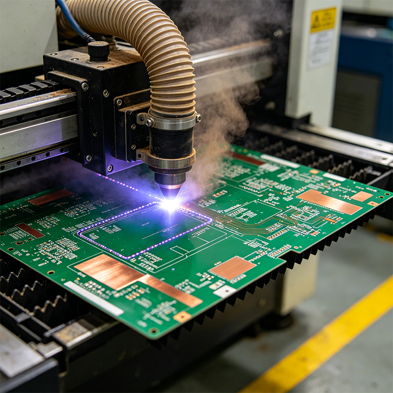
Rigid-flex is used across many industries:
Drone Flight Controllers: Rigid sections hold processors and sensors; flex sections connect motors and power modules.
Medical Endoscopes: The probe is tiny — cameras and LEDs must fit in a few millimeters.
Foldable Phones: Hinge cables must survive repeated bending.
Automotive Sensors: In high-vibration environments, connector-free rigid-flex is much more reliable than traditional solutions.
Aerospace: Satellites and aircraft demand extreme reliability and minimal weight.
Wearables: Smartwatches, AR glasses — space is extremely tight, and rigid-flex is the only choice.
Rigid-flex design is completely different from rigid board design. Here are the core rules:
1. No Components or Vias in Bend Areas
This is the most important rule. Solder joints and plated vias crack under repeated bending. All components and vias must stay out of the flex zone.
2. Bend Radius Must Be Sufficient
Bend it too tight, and the copper cracks. For dynamic bending, the bend radius must be at least 10 times the material thickness. For static bends, at least 6 times.
3. Trace Direction Matters
Traces should run perpendicular to the bend line, not parallel. This distributes stress more evenly.
4. Plan Stackup Early
Rigid-flex stackups are more complex than rigid boards. You must define which areas are rigid, which are flex, and how layers transition between them before you start.
5. Tighter Manufacturing Tolerances
Rigid-flex manufacturing tolerances are tighter than standard rigid boards.
Rigid-flex has dedicated industry standards. The most important is IPC-2223 — the sectional design standard for flexible printed boards. For specific applications like high-reliability medical devices, there are companion standards like IPC-6013EM.
We are not a standard rigid-only PCB shop. We are a one-stop manufacturer that designs and makes flexible PCBs, rigid-flex boards, HDI high-frequency boards, and then does full PCBA.
All in-house: Rigid-flex fabrication and PCBA assembly under one roof. No hand-offs.
Over a decade of rigid-flex experience: We know how to avoid rigid-flex transition cracks, control lamination alignment, and design proper bend area reinforcements.
High-precision manufacturing: Minimum trace/space 0.05mm, minimum laser blind via 0.075mm. Supports 1-order to any-layer HDI.
High-frequency material experience: Rogers, PTFE, LCP — for 5G and radar applications.
Dedicated rigid-flex SMT line: Rigid carriers, high-precision placement, 3D SPI, and AOI.
Free DFM review: Send your design files, get a DFM report within 24 hours — including bend area design, lamination alignment, and stackup manufacturability.
Three simple steps:
Send your files: PCB design files, BOM, special requirements (bend radius, impedance, materials, etc.).
We review and quote: Within 24 hours, you'll receive a DFM report, stackup recommendation, and sample/volume pricing.
Sample, then scale: We build 10-20 samples. You test functionality and bend reliability. Then we move to volume.
Rigid-flex is the unsung hero of high-end electronics — you rarely notice it, but it's quietly working inside drones, endoscopes, foldable phones, and automotive sensors. The global rigid-flex PCB market was valued at approximately $2.46 billion in 2025** and is projected to reach **$3.47 billion by 2032.
If you're designing a product that needs to bend, has tight space constraints, or demands high reliability, send us your requirements. We won't push a contract — we'll first run a free DFM review and let our expertise speak.
When you contact us, please include:
Product type and application
Whether dynamic bending is required
Estimated annual quantity (samples, small batch, or mass production)
We'll give you an honest answer — what we can do, what we can't, and how to modify your design to make it work.

Kaboer manufacturing PCBs since 2009. Professional technology and high-precision Printed Circuit Boards involved in Medical, IOT, UAV, Aviation, Automotive, Aerospace, Industrial Control, Artificial Intelligence, Consumer Electronics etc..


 English



 Wechat
 +86 13670210335
 +86 13670210335
 E-mail