
Date: 2026-07-29
You've definitely seen a circuit board before. Green, stiff, covered in copper traces and solder points. But have you ever wondered: what is the board itself actually made of? Why are some boards green and rigid, while others are yellow and can bend? Why do some boards handle 5G signals while others struggle with WiFi?
The answer is all in the materials.
A circuit board isn't a single piece of "plastic." It's a composite of multiple materials precisely laminated together. The material you choose determines how much heat the board can handle, how fast signals can travel, and whether it can bend. In this guide, I'll walk you through the most common PCB materials. Plain English, no fluff.
The substrate is the most important part of a circuit board — it's the skeleton. All copper traces and components sit on it. The substrate determines heat resistance, flexibility, and frequency capability.
1. FR4 — The Industry Workhorse, Used in 80% of Boards
FR4 is the most widely used PCB material in the world — 70-80% of all circuit boards use it.FR4 stands for "Flame Retardant 4" — it doesn't catch fire easily.It's made from woven fiberglass cloth and epoxy resin pressed together — like "layers of glass fabric glued together and pressed into a board."
Why is FR4 so popular? Three words: cheap and good enough. It's affordable, easy to process, and performs well for most everyday electronics — appliances, industrial controls, automotive ECUs, IoT devices.
Key FR4 specs: Glass transition temperature (Tg) is typically 130-140°C, with high-Tg versions reaching 170-180°C — above this, the board starts to soften.Dielectric constant (Dk) is 4.2-4.8, and dissipation factor (Df) is 0.015-0.025.But FR4 has a clear weakness: it struggles above 3-6GHz — signal loss becomes too high.
2. Polyimide (PI) — The Soul of Flex Boards
FR4 is rigid — it doesn't bend. Flexible circuit boards use polyimide (PI) film — DuPont's Kapton® is the most well-known brand.It withstands 260°C, survives hundreds of thousands of bend cycles, and has excellent dielectric properties.
Polyimide is used in flexible PCBs and rigid-flex boards — wearables, foldable displays, medical implants, aerospace.The downside: expensive and harder to process.
3. Rogers — The King of High Frequency, Standard for 5G and Radar
FR4 struggles above 3-6GHz. 5G, radar, and satellite communications need low-loss materials. Rogers is the king of high-frequency applications.Rogers uses ceramic-based or hydrocarbon materials instead of fiberglass.Its dielectric constant can be as low as 2.2-3.5, with loss factors as low as 0.001-0.004.
The upside is exceptional signal quality and minimal loss. The downside? Expensive. Rogers costs 5-10 times more than FR4.That's why it's only used where absolutely necessary — 5G mmWave antennas, automotive radar, aerospace communications.
4. Metal Core — The Heat Expert
If your product has high-power LEDs or components that generate serious heat, standard FR4 won't cut it — FR4's thermal conductivity is only 0.3-0.4 W/m·K.You need metal-core PCBs.
The most common is aluminum-core — thermal conductivity of 1-3 W/m·K, several times better than FR4.It's made of three layers: copper foil, insulation, and aluminum base. The aluminum pulls heat away quickly.Common in LED lighting, automotive lighting, and power modules.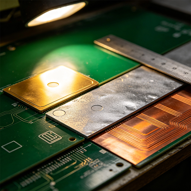
5. Ceramic Substrates — Extreme Environments
Ceramic substrates (alumina, aluminum nitride, etc.) offer extremely high thermal conductivity, withstand over 800°C, and have CTE that perfectly matches silicon.The downside: extremely expensive and complex to process.Used in aerospace, military, and extreme power applications.
The substrate is the skeleton. Copper foil is the veins — it carries current and signals.Copper thickness is measured in ounces (oz) . Common thicknesses: 0.5oz (~18μm), 1oz (~35μm), 2oz (~70μm). 1oz is the most common.
Solder mask is the green (or red, blue, black) protective layer you see, commonly called "green oil."Silkscreen is the white text and symbols — telling you which component goes where.
| Material | Heat Resistance | Flexible? | Cost | Best For |
|---|---|---|---|---|
| FR4 | 130-180°C | No | Low | Most everyday electronics |
| High-Tg FR4 | 170-180°C | No | Medium | Lead-free soldering, automotive |
| Polyimide (PI) | 260°C+ | Yes | High | Flex boards, wearables, medical |
| Rogers | High-frequency | No | Very High | 5G, radar, RF |
| Aluminum-core | Excellent heat dissipation | No | Medium | LED lighting, power circuits |
| Ceramic | >800°C | No | Very High | Military, aerospace, extreme environments |
A circuit board isn't one material — it's a combination: skeleton (substrate) + veins (copper) + jacket (solder mask and silkscreen). The material you choose determines whether your product can handle heat, run fast signals, or bend.
Most everyday products → FR4 — cheap and good enough
Need bending, thin and light → Polyimide (PI) — the soul of flex boards
5G, radar, high frequency → Rogers — the high-frequency king
LED, high power → Aluminum-core — the heat expert
Military, aerospace, extreme → Ceramic — the ultimate choice

Kaboer manufacturing PCBs since 2009. Professional technology and high-precision Printed Circuit Boards involved in Medical, IOT, UAV, Aviation, Automotive, Aerospace, Industrial Control, Artificial Intelligence, Consumer Electronics etc..


 English



 Wechat
 +86 13670210335
 +86 13670210335
 E-mail