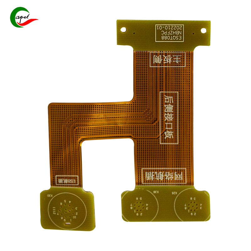
In the design and manufacturing of flexible printed circuits (FPCs), the structure of copper traces plays a critical role in product performance. Solid copper and mesh copper (also known as grid copper) are two common designs, each with distinct characteristics. Below is a detailed analysis of their differences in functionality, applications, and impacts on production and performance.
Solid copper’s key strength lies in its dual role: enhancing current transmission and providing electromagnetic shielding.
- Current Transmission: Its continuous, unbroken copper layer minimizes electron resistance, enabling efficient conduction of high currents. This makes it ideal for circuits requiring stable high-current supply.
- Electromagnetic Shielding: The thick, continuous copper layer acts as a "barrier," effectively blocking external electromagnetic interference (EMI) from entering the circuit and reducing EMI radiation from the circuit itself—ensuring signal purity.
Solid copper is widely used in low-frequency, high-current scenarios, such as:
- Traditional power supply circuits
- Basic low-frequency signal transmission circuits
- Simple circuits requiring strong EMI protection (common in standard copper foil applications).
However, it has notable limitations: During wave soldering, the large, concentrated heat absorption area of solid copper can cause board warping or even delamination, damaging structural integrity and performance. This restricts its use in applications with strict soldering requirements.
Example: In a 2-layer FPC, the top layer may feature copper traces, while the bottom layer uses solid copper. This setup meets basic current and shielding needs but requires caution to avoid soldering-induced deformation.

Mesh copper prioritizes electromagnetic shielding over current enhancement. Its grid-like structure, while reducing current-carrying capacity, offers unique benefits:
- Heat Dissipation: The grid design reduces copper mass, allowing faster heat dissipation—critical for heat-intensive circuits to maintain stable operating temperatures.
- Electromagnetic Shielding: With properly designed grid spacing, it acts like a "sieve," blocking specific frequency bands of electromagnetic signals effectively.
Mesh copper is suitable for scenarios needing EMI shielding but with lower current demands and a focus on heat dissipation. However, grid spacing is critical:
- Too Small Spacing: Increases alignment difficulty in multi-layer boards, raising production errors and defect rates.
- Too Large Spacing: Weakens shielding effectiveness, as the "sieve" becomes too porous to block EMI.
Example: In a 4-layer FPC, layers 1, 2, and 4 might use mesh copper. Proper spacing balances shielding, heat dissipation, and production feasibility, ensuring overall performance.
Copper design significantly affects circuit impedance. With identical project requirements and materials:
- The impedance difference between solid copper and mesh copper reference layers is typically 20–30 ohms, due to varying electron flow paths and resistance.
- Mesh copper impedance is further influenced by trace width and grid spacing: Narrower traces or smaller spacing increase impedance; wider traces or larger spacing reduce it.
- High Impedance Requirements: Choose mesh copper to control signal transmission speed and characteristics.
- Low Impedance Requirements: Opt for solid copper to prioritize smooth current flow.
Engineers must calculate and adjust these parameters to match circuit performance goals, ensuring stable signal transmission.
Solid copper and mesh copper each have unique applications and trade-offs. When designing FPCs, factors like current demands, EMI environment, heat dissipation needs, impedance requirements, and production complexity must be balanced to create high-performance, reliable flexible circuits.
Founded in 2009, our company has deep roots in the production of various circuit boards. We are dedicated to laying a solid electronic foundation and providing key support for the development of diverse industries.
Whether you are engaged in electronic manufacturing, smart device R&D, or any other field with circuit board needs, feel free to reach out to us via email at sales06@kbefpc.com. We look forward to addressing your inquiries, customizing solutions, and sincerely invite partners from all sectors to consult and collaborate, exploring new possibilities in the industry together.