Date: 2025-10-11
Alright, let's talk about rigid-flex. We all love it for solving tough packaging problems. But I've seen too many projects get bit by the same two issues: a bad transition from rigid to flex, and picking the wrong flexible material. Get these wrong, and your field failure rate will skyrocket. Get them right, and you've got a rock-solid board.
Here’s my no-BS guide from the trenches.
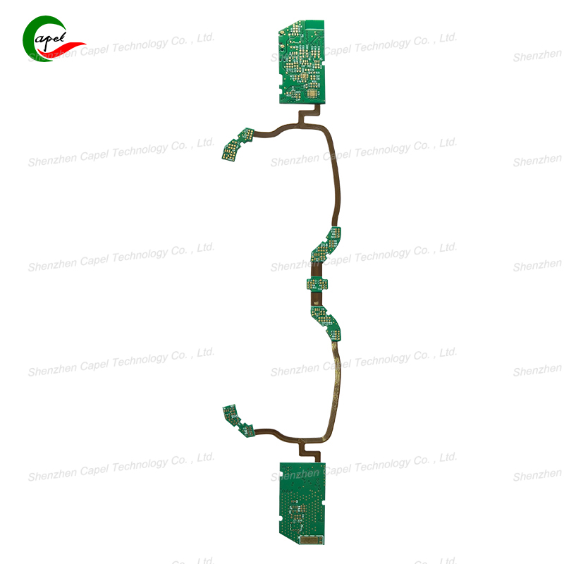
That little area where the stiff FR-4 meets the flexible polyimide? That's where your board will break. It's a stress magnet. Here’s how I design it to last.
1. Slope It, Don't Chop It.
I can't believe I still see 90-degree cuts. It's like trying to fold a piece of paper back and forth on a sharp crease—it fails fast. You need a smooth, tapered transition.
My Go-To: A 45-degree angle works beautifully for most apps. Think of it like a highway off-ramp instead of a cliff edge for the stress.
Why Bother? In one project for a foldable display, going from a straight cut to a 45-degree taper increased our cycle life by a factor of 3. The stress just doesn't have that one spot to focus on anymore.
2. Stiffen It Up (Just a Little).
Sometimes the flex needs a little backup. Adding a strategic stiffener across the joint is like putting a knee brace on it.
What I Use: Polyimide stiffener if I need to keep some flexibility. FR-4 if I just need to make that specific spot stiffer. I typically spec a 0.002" thick piece.
Coverage is Key: The stiffener can't just sit on the joint. I have it run about 5mm onto the rigid board and 5mm onto the flex. That way it truly bridges the two worlds. We used this trick on a car door module PCB that sees constant bending, and it passed 10k cycles without a hiccup.
3. Be Smart About Your Traces.
You can't just route willy-nilly through this area. The layout here is a survival game.
Give 'em Space: My number one rule: no traces within 0.05" (about 1.3mm) of the transition line. That's the danger zone.
Fat Traces Save Lives: Okay, maybe not lives, but definitely your product. I widen all traces in the transition by at least 20%. That 0.005" trace becomes 0.006". The extra copper does wonders for fatigue resistance. On a recent wearable project, this simple change alone eliminated our early-life flex failures.

4. The Bend Radius Isn't a Suggestion.
This is physics, people. Bend it too tight, and you will destroy the copper. It's not a matter of if, but when.
My Golden Rule: The minimum inside bend radius should be at least 6x the total thickness of the flex section. If your stack-up is 0.2mm thick, don't bend it tighter than a 1.2mm radius. And I add a 25% safety margin for anything that's going to move constantly.
Talk to Your ME: This is critical. You have to get this number into the mechanical designer's hands early. I once had a ME design a gorgeous hinge that bent my PCB to a 0.5mm radius. It was a very expensive paperweight.
Picking your flex core material is a fundamental choice. It boils down to one question: How hot will it get?
Polyimide (PI): The Tough Guy
This is what you use when failure is not an option. It's the industry standard for a reason.
The Killer Feature: Handles a soldering iron like a champ. You can run reflow profiles all day long. Its continuous temp rating goes up to 260°C. It's just stable.
Polyester (PET): The Budget Option
It's cheap and flexible, but it has a kryptonite: heat.
The Deal-Breaker: Don't even think about standard lead-free reflow. PET starts to shrink and degrade above 150°C. It's fine for things that are assembled with conductive epoxy or low-temp solder, but it's a headache for mainstream SMT.
The Real-World Choice:
I only use PET for one-off, cost-sensitive, low-heat applications. Think of a simple LED strip inside a cool-running consumer gadget. If the device has any real computing power, a power management IC, or will live in a hot environment (like a car), PI is the only sane choice.
I remember a project where a competitor tried to save $0.50 per board by using PET in a set-top box. The boards near the power supply started delaminating after 6 months in the field. The cost of the recall made that $0.50 saving look pretty stupid. Just use the PI.
Let's take a hypothetical fitness tracker band.
The Challenge: A small rigid board for the brains, connected to a flex circuit that wraps around your wrist, bending thousands of times.
The Execution:
Transition: We used a gentle taper and a thin PI stiffener right where the main board meets the band.
Traces: All sensor traces in the transition were widened and kept away from the edge.
Bend Radius: The industrial design was dictated by our 2mm minimum bend radius spec.
Material: PI. Why? Because the device might be left in a hot car, and we need it to survive for years.
The Result: A reliable product that doesn't come back for warranty repairs.
Designing reliable rigid-flex isn't magic. It's about respecting the physics of bending and heat.
Treat the transition zone with care. Taper it. Reinforce it. Route traces wisely.
Don't fight the bend radius. It's a law, not a guideline.
When in doubt, choose Polyimide. The cost savings from PET are rarely worth the risk.
Stick to these principles, and you'll build boards that work on your bench and keep working out in the real world.
related link:
Kaboer manufacturing PCBs since 2009. Professional technology and high-precision Printed Circuit Boards involved in Medical, IOT, UAV, Aviation, Automotive, Aerospace, Industrial Control, Artificial Intelligence, Consumer Electronics etc..