
Date: 2026-07-21
You've finished your PCB layout. Components placed, traces routed. Next step: send it to a factory for production. But factories can't just open your design software's project files — they need a universal format that every piece of software and every machine can read. That's where PCB manufacturing files come in.
Many people confuse "PCB files" with "Gerber files." They're not the same thing. In this guide, I'll explain what PCB files are, what formats exist, how to generate them, and how to submit them to a manufacturer. Plain English, no fluff.
A PCB file (typically with a .pcb extension, or a proprietary format) is the original design file you save in your EDA software (Altium Designer, KiCad, PADS, etc.) after completing your board layout.
It contains all the design information — component positions, trace routing, net connectivity, layer stackup, and more. But there's a catch: manufacturing equipment cannot directly read PCB file formats. Different software uses different file extensions — Altium uses .pcbdoc, Allegro uses .brd, KiCad uses .kicad_pcb — and factories can't install every design tool for every customer.
So what you send to the factory cannot be the original PCB source file — it has to be converted into standardized manufacturing files.
Converting your PCB source files into something factories can read comes down to three main options: Gerber, ODB++, and IPC-2581.
1. Gerber — The Industry Standard
Gerber is the most universal and fundamental file format in PCB manufacturing. It saves each layer of the circuit board (copper layers, solder mask, silkscreen, etc.) as a separate file. For a double-sided board, you need files for top copper, bottom copper, top solder mask, bottom solder mask, top silkscreen, bottom silkscreen, board outline, and drill data.
Each Gerber file describes just one layer of the PCB. Modern factories universally require the RS-274X format, because it integrates both graphical data and aperture (D-code) information into a single file. The older RS-274D format requires a separate D-code file and is now obsolete.
Drill information is not included in Gerber files — it requires a separate Excellon drill file (.drl) that specifies hole positions, sizes, and types.
Gerber's biggest advantage is universal support — every PCB factory can process it. The downside: it's a collection of "blind" images. It knows "there's a line at coordinates X,Y," but it doesn't know "this line is the USB_D_P signal". CAM engineers have to manually import layers, guess the stackup order, and reverse-engineer the netlist to check for shorts — 90% of front-end PCB manufacturing errors happen during this translation process.
2. ODB++ — The Smarter Format
ODB++ is an intelligent data exchange format originally developed by Mentor Graphics. It packages all manufacturing data — PCB thickness, layer stackup, component placement, drill data, netlist, and more — into a single file package. It clearly distinguishes between pads, vias, and conductors, reducing data misinterpretation.
ODB++ is much smarter than Gerber. It's now the most widely used intelligent data exchange format in the PCB industry and the de facto standard. The downside: it's less universal than Gerber — some smaller factories may not support it.
3. IPC-2581 — The Open Standard
IPC-2581 is an XML-based open standard. It compresses design, fabrication, assembly, and test data into a single .xml file. Its biggest advantage: one file instead of the dozen or more required for Gerber. IPC-2581 also allows designers to export only a subset of data, making it extremely difficult to reverse-engineer. The downside: it's relatively new and less widely adopted than Gerber or ODB++.
If you're ordering a PCB, a complete file package typically includes:
Core files (required) :
Gerber files (all copper layers, solder mask, silkscreen, board outline)
Excellon drill file (.drl or .txt), including hole coordinates, diameters, and plating information
Supplementary files (strongly recommended) :
Bill of Materials (BOM) :Lists all components with part numbers, packages, and brands
Pick-and-Place file (Centroid) :Tells the placement machine where each component goes and its orientation
Fabrication notes :Board thickness, layer count, material (FR4), surface finish (ENIG/HASL), impedance requirements, etc.
PCB source file :As backup only — factories prioritize Gerber
When submitting, package all files into a single .zip or .rar archive, with a clear version number in the filename (e.g., V1.2_Gerber.zip). Include a readme.txt with any special process requirements.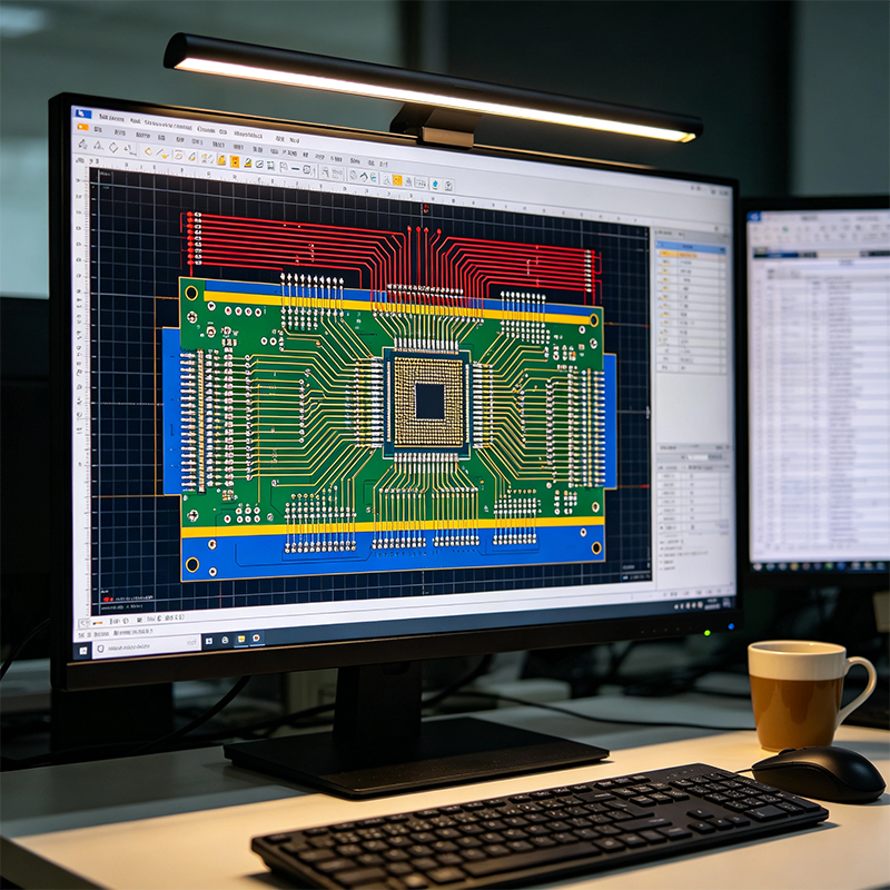
The exact steps vary by software, but the general process is the same:
Open your PCB file in the design software
Select "Export" or "Generate Manufacturing Files"
Choose the RS-274X format
Confirm every layer you need to export (copper layers, solder mask, silkscreen, board outline, etc.)
Export the Excellon drill file (ensure units match the Gerber files)
Package all files into a ZIP
Run a DRC (Design Rule Check) before exporting to catch opens, shorts, and clearance violations. After exporting, preview the Gerber files with a Gerber viewer to verify everything looks correct.
Sending only the PCB source file: The factory may not be able to open it
Missing solder mask or drill layers: Pads get covered or holes don't get drilled
Mixed units in Gerber and drill files (mm vs inches): All hole positions shift
Using PDF drawings instead of Gerber: Cannot be manufactured
A PCB file is your design software's project file — you can't send it directly to a factory for production. You need to convert it into standardized manufacturing files like Gerber, ODB++, or IPC-2581. Gerber is the most universal format — virtually every factory supports it. A complete manufacturing package typically includes Gerber layers + Excellon drill file + BOM + Pick-and-Place file + fabrication notes.
Next time you finish a board layout and need to send it to a factory, remember: don't just send your source file — export Gerber files, review them, package them in a ZIP, and upload. That one step will save you 90% of the back-and-forth communication and rework time.

Kaboer manufacturing PCBs since 2009. Professional technology and high-precision Printed Circuit Boards involved in Medical, IOT, UAV, Aviation, Automotive, Aerospace, Industrial Control, Artificial Intelligence, Consumer Electronics etc..


 English



 Wechat
 +86 13670210335
 +86 13670210335
 E-mail