
Date: 2026-07-28
You've designed a circuit board. Schematic checked. Layout polished. Every test passed. But when you run high-speed signals — USB won't connect, HDMI flickers, DDR memory throws errors — the system is unstable, on and off.
The culprit is often invisible: impedance mismatch.
In this guide, I'll explain what impedance matching is, why it matters, and how to get it right. Plain English, no fluff.
First, let's get one thing straight: what is "impedance"?
Simply put, impedance is the total opposition a circuit offers to alternating current (AC) . It's not resistance — resistance only "resists" current, while impedance combines the effects of resistors, capacitors, and inductors. More importantly, impedance changes with frequency — the higher the frequency, the more capacitors and inductors matter.
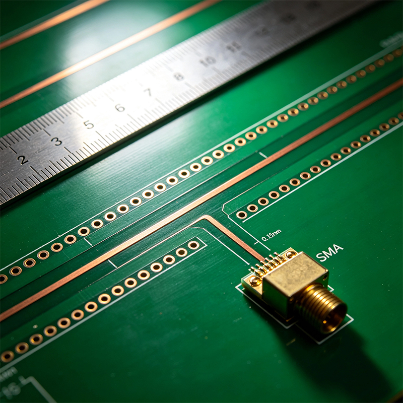
When signal frequencies climb above 1 Gbps, PCB traces stop behaving like ordinary "wires" and start behaving like transmission lines. Each trace has a characteristic impedance determined by its width, copper thickness, distance to the reference plane, and the dielectric constant of the surrounding material.
Impedance matching means keeping the source impedance, transmission line impedance, and load impedance all equal. When they don't match, some signal energy reflects back at the impedance change — like a wave hitting a wall and bouncing back. The reflected signal adds to the original, causing ringing, overshoot, data jitter, and in severe cases, eye diagram closure and system failure.
You might think "a few ohms off doesn't matter." It does.
A 10-15% impedance mismatch is strong enough to close an eye diagram and introduce bit errors. That USB interface you spent hours routing? It might not connect at all.
Impedance mismatch causes:
Signal reflections: Energy bounces back and forth, creating ringing and overshoot
Data jitter: Reflected signals interfere with timing, blurring the data eye
EMI: Reflected signals radiate noise like antennas
Higher power consumption: Reflected energy dissipates on the trace instead of being absorbed by the load
Not every trace needs controlled impedance. But these absolutely do:
USB 2.0/3.x: 90Ω differential
PCIe Gen1-5: 85Ω differential
HDMI: 100Ω differential
DDR4: 40Ω single-ended, 80Ω differential
Ethernet: 100Ω differential
Single-ended clocks and RF: 50Ω
If your board has any of these interfaces, skipping impedance matching is a gamble.
Impedance matching comes down to design and manufacturing.
During design:
Choose the right material: FR4 becomes lossy above 1-2GHz. High-frequency designs need low-loss materials like Rogers, Megtron, or PTFE. In 2026, Megtron 7 and PTFE are seeing significantly increased adoption.
Design the stackup: Impedance depends on trace width, copper thickness, dielectric thickness, and dielectric constant. Calculate these parameters during design — don't wait until manufacturing.
Use a field solver: Don't guess with formulas. Tools like Polar Si9000e calculate impedance accurately. Input correct material parameters and get the trace width you need.
Compensate for solder mask: On outer layer traces, solder mask changes the effective dielectric constant, lowering measured impedance by 3-8Ω. High-end designs must account for this.
Consider copper roughness: Above 10GHz, standard ED copper roughness effectively increases dielectric constant due to skin effect, dropping impedance by another 2-4Ω. High-end designs in 2026 are switching to HVLP (very low profile) copper.
During manufacturing:
Precise etching control: Outer layer traces need width compensation for etch factor — typically 0.35-0.5mil on outer layers.
Lamination thickness control: Prepreg flow and thickness variation are the main causes of impedance inconsistency across a board. Post-lamination dielectric thickness tolerance must be kept within ±8%.
Use impedance coupons: Factories place test coupons at the board edge and measure actual impedance with TDR (Time Domain Reflectometry). In 2026, impedance tolerance has tightened from ±10% to ±7% or even ±5%.
If your product uses flex PCBs or rigid-flex boards, impedance matching gets even harder.
Flex materials (polyimide PI) have a different dielectric constant than FR4 — FR4 is about 4.2-4.6, PI is about 3.4-3.6. When a signal crosses from the rigid section to the flex section, impedance changes. Flex boards also typically lack solid reference planes, making controlled impedance more difficult.
Key points for flex impedance control:
Consistent trace geometry: Width, copper thickness, and dielectric thickness must be tightly controlled
Account for bending: When a flex region bends, the polyimide compresses and impedance changes
Manage the rigid-flex boundary: Signals crossing from FR4 to PI need careful design to compensate for the impedance change
Tighter manufacturing tolerances: Flex dielectrics are only 12.5-25μm thick — a few microns of variation is a meaningful percentage change
Three major shifts are happening:
Speed ramping: Signal rates are pushing past 100Gbps. Under PAM4 modulation, impedance tolerance is tightening to ±5% or even ±3%.
Material upgrades: High-frequency materials like Megtron 7 and PTFE are seeing wider adoption, with narrower processing windows.
Structural complexity: Any-layer HDI and embedded resistor technologies are becoming more common, increasing non-uniformity.
The global impedance control PCB market was valued at $2.214 billion in 2025** and is projected to reach **$3.008 billion by 2032, growing at a 4.5% CAGR.
Impedance matching is the lifeline of high-speed PCB design. It's not optional — if your board has USB, HDMI, PCIe, DDR, or any signal above 1 Gbps, you need it.
Impedance matching comes down to precise design and tight manufacturing control. Choose the right materials, calculate the right parameters, and hold the right tolerances. On flex and rigid-flex boards, the challenge is even greater.
We are a custom manufacturer of flexible PCBs, rigid-flex boards, HDI high-frequency boards, and full PCBA services. From impedance calculation and stackup design to material selection and manufacturing verification, we handle the whole process — ensuring your high-speed signals run clean and stable. Have a high-speed PCB design or manufacturing need? Send us your design files — we'll do an impedance review and get back to you within 24 hours.

Kaboer manufacturing PCBs since 2009. Professional technology and high-precision Printed Circuit Boards involved in Medical, IOT, UAV, Aviation, Automotive, Aerospace, Industrial Control, Artificial Intelligence, Consumer Electronics etc..


 English



 Wechat
 +86 13670210335
 +86 13670210335
 E-mail