
Date: 2026-07-06
You're designing an electronic product. Maybe an industrial controller, an automotive system, a medical device, or a communication module that needs to survive extreme vibration. You open your design software, and a fundamental question appears: should I use through-hole components?
SMT dominates component placement today, and many assume through-hole technology is "obsolete." But the numbers tell a different story. The global through-hole passive components market was valued at approximately $39.92 billion in 2025** and is projected to reach **$42.5 billion in 2026, growing at a CAGR of 6.5%. By 2033, this market is expected to reach $66.62 billion.
Through-hole technology isn't disappearing—it's growing. In this guide, I'll explain what through-hole technology is, why high-end products still depend on it, and how to choose the right manufacturing partner. Plain English, no fluff.
Through-Hole Technology (THT) is a component mounting method where component leads are inserted through drilled holes in the PCB and soldered on the opposite side.
There are two types of holes:
Plated Through-Hole (PTH) : The hole wall is plated with copper for conductivity. Used for both component mounting and layer-to-layer connections.
Non-Plated Through-Hole (NPTH) : No copper plating, non-conductive. Used for mounting holes—screwing the board into an enclosure.
Think of it this way: SMT places a flower pot on the ground; THT plants a tree with roots through the soil. Roots go deeper and hold stronger.
Many engineers struggle with this choice. Here are the key differences:
| Feature | Through-Hole (THT) | Surface Mount (SMT) |
|---|---|---|
| Mounting | Leads pass through holes in the board | Components sit directly on the surface |
| Mechanical strength | Very strong — ideal for heavy components and high vibration | Moderate — relies on pad adhesion |
| Thermal management | Leads conduct heat through the board | Limited heat paths |
| Reliability | Extremely high — aerospace, military, medical | High — but susceptible to vibration and thermal stress |
| Repair/Rework | Relatively easy — standard soldering iron works | Difficult — especially fine-pitch and BGA |
| Automation | Semi-automated or manual | Highly automated |
| Cost | Higher component and labor costs | Lower component and assembly costs |
THT's core value is mechanical connection strength. This is why products that need to withstand vibration, frequent plugging/unplugging, high current, or extreme temperatures still choose THT.
THT is far more common than you might think:
Connectors and Interfaces: USB ports, power jacks, pin headers, terminal blocks. Anywhere that gets plugged and unplugged repeatedly uses THT. Plugging force goes directly into the leads — without THT, pads would tear off.
High-Power Components: Electrolytic capacitors, power transistors, transformers, relays. These components are large, heavy, and generate heat. Only THT provides sufficient mechanical strength and heat paths.
High-Reliability Products: Aerospace, military, medical devices, automotive ECUs. Extreme environments — high vibration, wide temperature swings, high humidity. One bad joint can cost lives. THT's reliability is unmatched.
Field-Serviceable Equipment: Industrial control cabinets, base stations, test instruments. These devices often last 10+ years and must be repaired on-site. THT components can be removed with a standard iron; SMT fine-pitch and BGAs require professional rework stations.
Hybrid Assembly: Most modern electronics use THT + SMT mixed — SMT for high-density sections, THT for connectors and power components. This hybrid approach balances miniaturization and reliability.
THT may seem simple, but several critical design factors matter:
1. Hole-to-Lead Matching
Holes too small and leads won't fit. Too large and joints are weak. IPC-2221 and IPC-2222 provide detailed guidelines. For standard thickness PCBs, the typical recommendation is 8-20 mils of clearance around the lead. Standard hole tolerance is typically ±0.075mm.
2. Annular Ring Width
The annular ring is the copper ring around the drilled hole. IPC standards specify minimum annular ring requirements. If the ring is too thin or missing, drill misalignment can sever the connection.
3. Through-Hole Fill Ratio
Per IPC standards, through-hole solder fill must reach at least 75%. Insufficient fill means solder hasn't fully penetrated — the joint lacks strength.
4. Aspect Ratio
Aspect ratio is board thickness divided by hole diameter. If this ratio is too large, plating copper can't reach the middle of the hole wall uniformly. Generally, keep the aspect ratio below 8:1 — high-end processes can go to 12:1 or higher.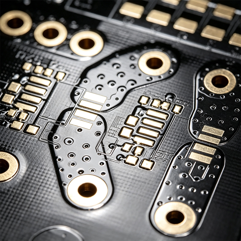
Through-hole quality and reliability are governed by a comprehensive IPC standards framework:
IPC-2221 (General Design) : Provides detailed guidelines on minimum annular ring size, land requirements, location tolerance, and other through-hole design elements
IPC-2222 (Rigid Board Design) : Works with IPC-2221, covering through-hole pad stack requirements
IPC-A-610 (Assembly Acceptability) : Defines Class 1/2/3 acceptance criteria for through-hole solder joints
IPC-J-STD-001 (Soldering Process) : Specifies soldering materials and process requirements
IPC-6012 (Rigid Board Performance) : Covers electrical and mechanical performance requirements for plated through-holes
IPC-A-610 is the most commonly used acceptance standard. Class 3 (high-reliability products) has the strictest requirements — fill ratio, wetting angle, and appearance are all tightly controlled.
We are not a standard SMT-only shop. We are a one-stop manufacturer that designs and makes flexible PCBs, rigid-flex boards, HDI high-frequency boards, and then does full PCBA. Through-hole technology is part of our everyday work.
All in-house: PCB fabrication, SMT, THT, wave soldering, selective soldering, and testing under one roof. Every step is under our control.
THT expertise: We've done hundreds of projects with THT components — connectors, electrolytic capacitors, power transistors, relays — with proven through-hole soldering experience.
Rigid-flex through-hole handling: Through-holes on rigid-flex boards are completely different from rigid boards. We know how to place them in transition zones and control stress.
IPC-compliant: We fabricate and inspect to IPC-6012, IPC-A-610, and IPC-J-STD-001 — Class 1, 2, and 3.
Hybrid assembly capability: SMT + THT mixed assembly is the norm for most products. We have complete SMT and THT lines to handle any mixed assembly requirement.
Free DFM review: Send your design files, get a DFM report within 24 hours — including hole size, annular ring, aspect ratio checks.
Three simple steps:
Send your files: Gerbers, BOM (mark THT components), special requirements.
We review and quote: Within 24 hours, you'll receive a DFM report and pricing.
Sample, then scale: We build 10-20 samples. You test. Then we move to volume.
Through-hole technology isn't "obsolete" — it's a necessity for high-reliability products. The global through-hole passive components market reached $39.92 billion in 2025, growing at 6.5% annually. Connectors, high-power components, aerospace, automotive, industrial equipment — these sectors still depend on THT.
If you're designing a product that needs high reliability, high power, or frequent plugging/unplugging, send us your requirements. We won't push a contract — we'll first run a free DFM review and let our expertise speak.
When you contact us, please include:
Product type and application
Whether THT components are required (connectors, electrolytic capacitors, power devices, etc.)
Estimated annual quantity (samples, small batch, or mass production)
We'll give you an honest answer — what we can do, what we can't, and how to modify your design to make it work.

Kaboer manufacturing PCBs since 2009. Professional technology and high-precision Printed Circuit Boards involved in Medical, IOT, UAV, Aviation, Automotive, Aerospace, Industrial Control, Artificial Intelligence, Consumer Electronics etc..


 English



 Wechat
 +86 13670210335
 +86 13670210335
 E-mail