
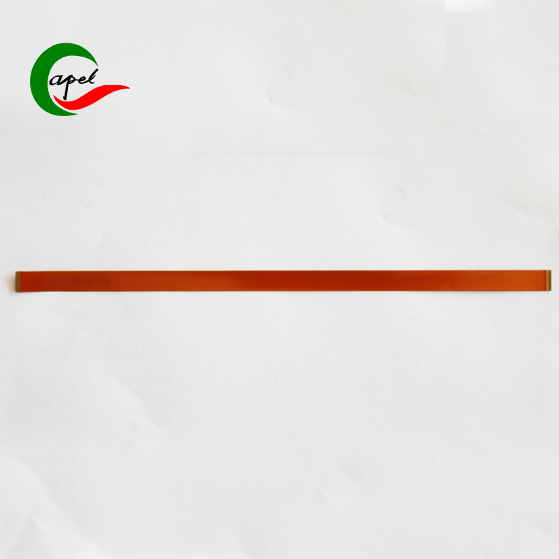

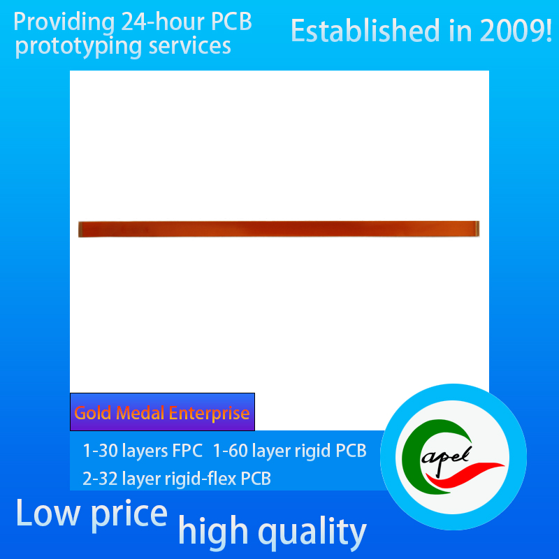
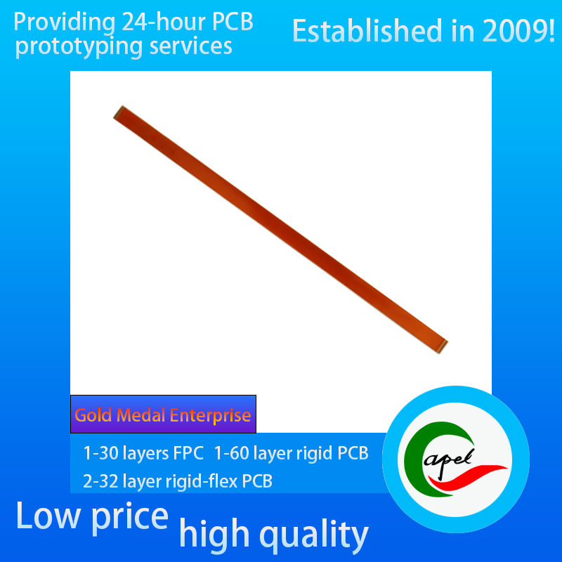
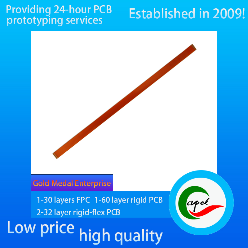
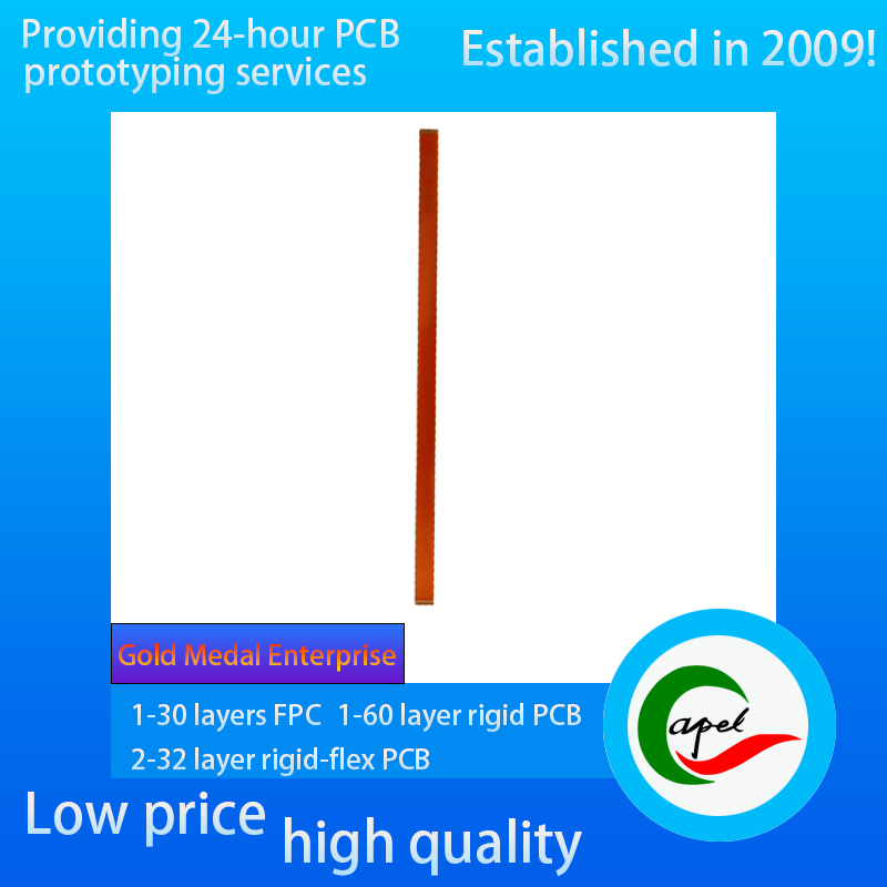

Industrial Control Device Lineup FPC
A short introduction:
Type: Industrial Control Device Lineup FPC
Minimum Line Width/Line Spacing: 0.13mm/0.12mm
Number of Layers: 1 Layer
Thickness: 0.13mm
Surface Finish: Immersion Gold 1 Micro Inch
Kaboer's Services:
Support Customized 1-30 Layer FPC Flexible PCB, 2-32 Layer Rigid-Flexible PCB, 1-60 Layer Rigid PCB, Reliable Fast Turnaround PCB prototyping, rapid SMT PCB assembly
Industries we serve:
Medical devices, IoT, TUT, drones, aerospace, automotive, telecom, consumer electronics, military, aerospace, industrial control, AI, electric vehicles, etc. ......
If you have related needs, please feel free to send us an email by clicking the button below.
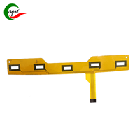
Type: Industrial control equipment special wiring flexible circuit board (FPC), designed for industrial-grade signal and power transmission, adapted to sensor data acquisition, motor control commands issued, power distribution between modules and other core scenarios. Whether it is a CNC machine tool axis control module connection, automated production line IO interface expansion, or intelligent warehousing equipment sensor array wiring, can be flexible to fit the equipment inside the small gaps (such as chassis partition, module gap) and irregular surfaces, instead of the traditional wiring harness or flat cables, in the reduction of the wiring volume (save 40% space) while reducing the risk of failure due to cable entanglement, friction (50% reduction in failure rate). Reduces the risk of failure due to cable entanglement and friction (50% reduction in failure rate).
Minimum wire width/spacing: industrial-grade accuracy of 0.13mm/0.12mm. This parameter is specially optimized for industrial control signal characteristics: 0.13mm line width ensures that control signals (such as 24V switching output from PLC) and low-power power supply (≤1A) have lower transmission loss (voltage drop ≤0.2V/m), avoiding false alarms due to insufficient power supply to the sensors; 0.12mm line spacing in the limited width of the wiring (e.g., 10mm width can accommodate ≥30 lines) to achieve dense 0.12mm wire spacing to achieve dense wiring within a limited wiring width (e.g. 10mm width can accommodate ≥30 lines), support “signal + power + ground” parallel transmission, and isolate digital signals from analog signals through a reasonable spacing (isolation ≥45dB), to avoid false triggering of signals due to electromagnetic interference when the motor is started (false operation rate ≤0.01 times / 10,000 hours).
Layers: 1-layer structural design, through streamlining the layout to achieve the dual goals of “high reliability + easy maintenance”:
Single-layer wiring reduces the number of inter-layer connection points (e.g., via holes), reducing the risk of circuit breakage due to inter-layer stripping (compared with the multi-layer design of the 60% reduction in the number of points of failure), especially suitable for vibration-frequent industrial scenarios (e.g., punching presses, forging presses);
wiring Visible wire routing facilitates troubleshooting during equipment maintenance (e.g. visual inspection of broken wires, wear and tear) and shortens downtime for maintenance (average maintenance time ≤ 30 minutes).
At the same time, a large area of grounding copper foil and signal lines adjacent to the design, the formation of “signal - ground” shielding structure, to inhibit RF interference in the industrial environment (EMI suppression ≥ 40dB).
Thickness: 0.13mm ultra-thin characteristics, perfectly adapted to the industrial control equipment, “compact space + dynamic adaptation” needs. In modular equipment (such as stacked IO modules), can significantly reduce the occupation of the row of wires on the module spacing (module gap can be reduced to 1mm); in the need to bend parts (such as equipment door axle, movable arm connection), can adapt to the minimum bending radius R = 3mm of repeated deformation (support ≥ 100,000 times ± 90 ° bending), to avoid fatigue breakage of row of wires due to the equipment opening and closing, and at the same time to maintain the line resistance At the same time to maintain line resistance stability (change rate ≤ 1%).
Surface treatment: the use of immersed gold 1 micro-inch process (nickel layer thickness ≥ 3μm, gold layer thickness ≥ 0.025μm), bringing multiple industrial-grade advantages:
excellent conductivity of the gold layer, the contact resistance of ≤ 30mΩ, to ensure the stability of the transmission of low-level signals (such as the sensor output of the 4-20mA current signals), the measurement error is ≤ 0.5%;
immersed gold plating layer of corrosion resistance, can be resistant to industrial workshops, oil and dirt, Coolant, dust erosion (through the 72-hour neutral salt spray test without corrosion), to adapt to the relative humidity of 95% (no condensation) of the humid environment;
to enhance the reliability of connector insertion and extraction, the low coefficient of friction of the gold layer (≤ 0.15) to reduce insertion and extraction of wear and tear, so that the life of the connector to increase to ≥ 500 times the insertion and extraction (the traditional tin-plated layer of about 300 times) to reduce the frequency of maintenance and replacement.
| Category | Process Capability | Category | Process Capability |
| Production Type |
Single layer FPC / Double layers FPC Multi-layer FPC / Aluminum PCBs Rigid-Flex PCB |
Layers Number |
1-30 layers FPC 2-32 layers Rigid-FlexPCB 1-60 layers Rigid PCB HDI Boards |
| Max Manufacture Size |
Single layer FPC 4000mm Double layers FPC 1200mm Multi-layers FPC 750mm Rigid-Flex PCB 750mm |
Insulating Layer Thickness |
27.5um /37.5/ 50um /65/ 75um / 100um / 125um / 150um |
| Board Thickness |
FPC 0.06mm - 0.4mm Rigid-Flex PCB 0.25 - 6.0mm |
Tolerance of PTH Size |
±0.075mm |
| Surface Finish |
Immersion Gold/Immersion Silver/Gold Plating/Tin Plating/OSP |
Stiffener | FR4 / PI / PET / SUS / PSA/Alu |
| Semicircle Orifice Size | Min 0.4mm | Min Line Space/ width | 0.045mm/0.045mm |
| Thickness Tolerance | ±0.03mm | Impedance | 50Ω-120Ω |
| Copper Foil Thickness | 9um/12um / 18um / 35um / 70um/100um |
Impedance Controlled Tolerance |
±10% |
|
Tolerance of NPTH Size |
±0.05mm | The Min Flush Width | 0.80mm |
| Min Via Hole | 0.1mm |
Implement Standard |
GB / IPC-650 / IPC-6012 / IPC-6013II / IPC-6013III |


![]()
Kaboer manufacturing PCBs since 2009. Professional technology and high-precision Printed Circuit Boards involved in Medical, IOT, UAV, Aviation, Automotive, Aerospace, Industrial Control, Artificial Intelligence, Consumer Electronics etc..


 English
 Automotive Navigation Single-Sided Flexible PCB
 Automotive Navigation Single-Sided Flexible PCB
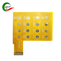 Single-Sided Flexible PCB for Automotive Applications
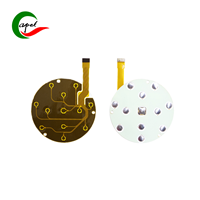 Medical Device Single-Sided Flexible PCB
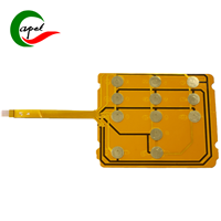 Single-Sided Keypad Flexible PCB
 Single-Sided Flexible PCB for Communication Equipment


 Wechat
 +86 13670210335
 +86 13670210335
 E-mail