
CAPEL SMT Assembly Service
FPCs & PCBs & Rigid-Flex PCBs
Expedited PCB Assembly Services
√ 1-2 days quick turn pcb assembly prototype
√ 2-5 days online components from reliable suppliers
√ Fast response for technical support and advice
√ BOM analysis to ensure component uniformity and data integrity
SMT ASSEMBLY
Quick Turn Prototype
Mass Production
After-Sale Service 24 online
CAPEL Production Process
Material Preparation→ Solder Paste Printing→ SPI→ IPQC→ Surface Mount Technology→ Reflow Soldering
↓
Protection and Packaging ← After Welding ← Wave Soldering ← X-ray ←AOI ← First Artide Testing
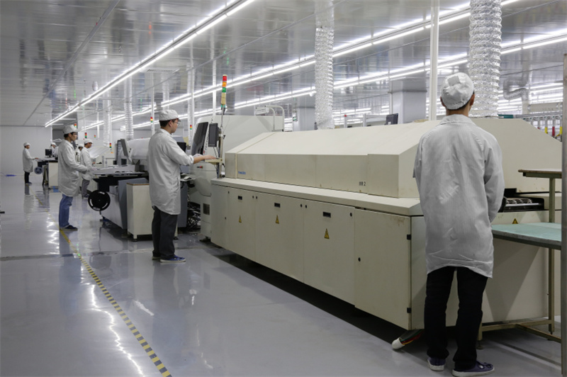
CAPEL SMT/DIP line
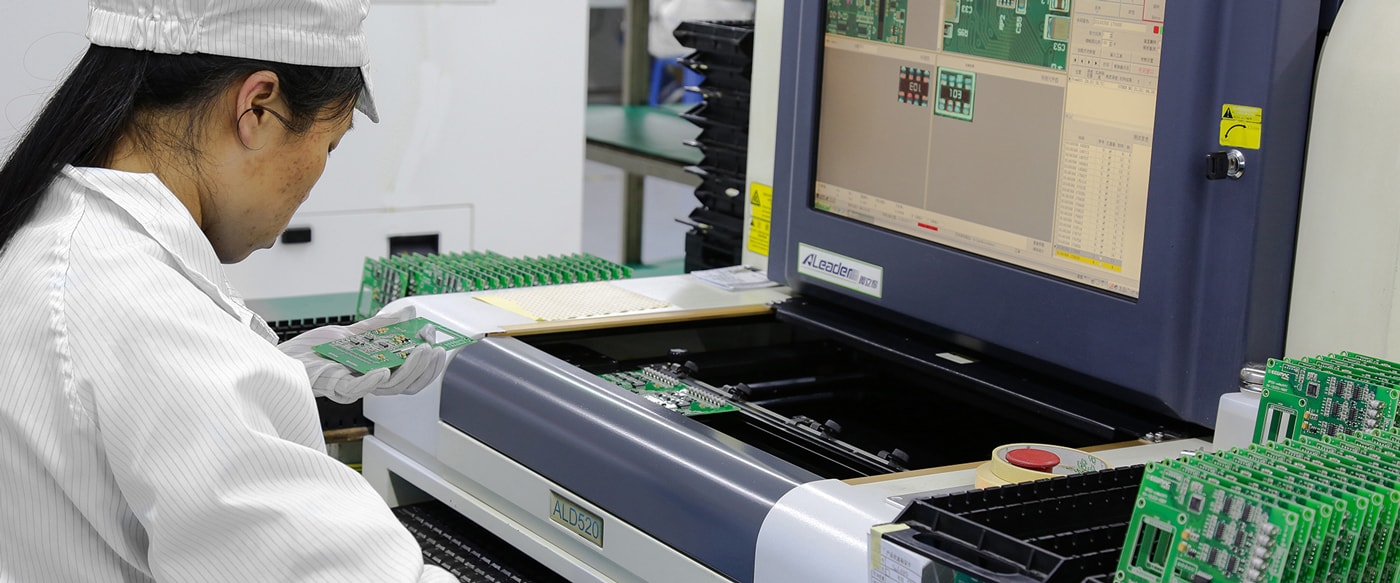
● IQC(Incoming Quality Control)
● IPQC(ln-process Quality Control)/FAl test
● Visual Inspection after reflow oven/AOl
● CT equipment
● Visual Inspection before reflow oven
● QA random inspection
● OQC (Out-going Quality Control)
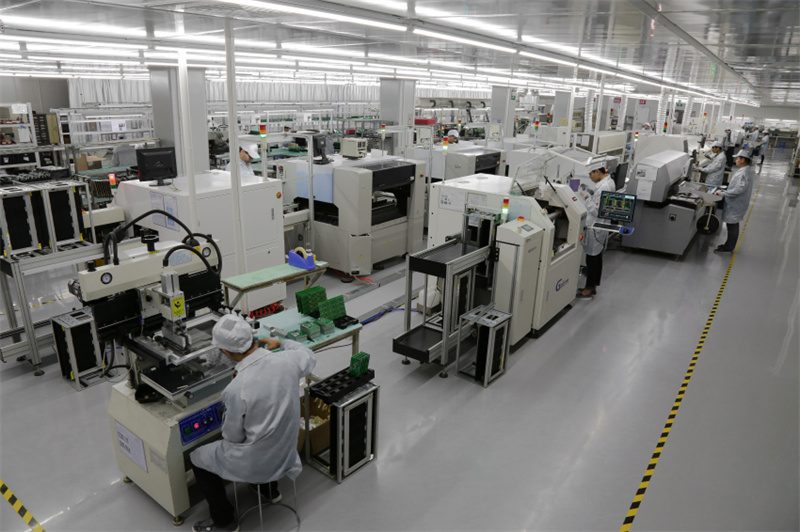
CAPEL SMT FACTORY
● Online Quote in Minutes
● 1-2Days quick turn pcb assembly prototype
● Fast response for technical support and advice
● BOM analysis to ensure component
● uniformity and data integrity
● 7*24 Online Customer Service
● High-Performance Supply Chain
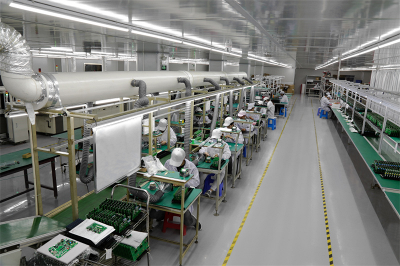
CAPEL SOLUTION EXPERT
● PCB Fabrication
● Components Souring
● SMT&PTH Assembly
● Programming, Function Test
● Cable Assembly
● Conformal Coating
● Enclosure Assembly etc.
CAPEL PCB Assembly Process Capability
| Category | Details | |
| Lead Time | 24 hours Prototyping,the delivery time of small-batch is about 5 days. | |
| PCBA Capacity | SMT patch 2 million points/day, THT 300,000 points/day, 30-80 orders /day. | |
| Components Service | Turnkey | With mature and effective component procurement management system, we serve PCBA projects with high-cost performance. A team of professional procurement engineers and experienced procurement personnel is responsible for the procurement and management of components for our customers. |
| Kitted or Consigned | With a strong procurement management team and component supply chain, Customers provide us with components, we do the assembly work. | |
| Combo | Accept components or special components are provided by customers. and also components resourcing for customers. | |
| PCBA Solder Type | SMT, THT, or PCBA soldering services both. | |
| Solder Paste/Tin Wire/Tin Bar | lead and lead-free (RoHS compliant) PCBA processing services. And also provide customized solder paste. | |
| Stencil | laser cutting stencil to ensure that components such as small-pitch ICs and BGA to meet IPC-2 Class or higher. | |
| MOQ | 1 piece, but we advise our customers to produce at least 5 samples for their own analysis and testing. | |
| Component Size | • Passive components: we are good at fitting the inch 01005 (0.4mm * 0.2mm), 0201 such small components. | |
| • High-precision ICs such as BGA: We can detect BGA components with Min 0.25mm spacing by X-ray. | ||
| Component Package | reel, cutting tape, tubing, and pallets for SMT components. | |
| Maximum Mount Accuracy of Components (100FP) | Accuracy is 0.0375mm. | |
| Solderable PCB Type | PCB (FR-4, metal substrate), FPC, Rigid-flex PCB, Aluminum PCB,HDI PCB. | |
| Layer | 1-60(layer) | |
| Maximum processing area | 545 x 622 mm | |
| Minimumboardthickness | 4(layer)0.40mm | |
| 6(layer) 0.60mm | ||
| 8(layer) 0.8mm | ||
| 10(layer)1.0mm | ||
| Minimum line width | 0.0762mm | |
| Minimum spacing | 0.0762mm | |
| Minimum mechanical aperture | 0.15mm | |
| Hole wall copper thickness | 0.015mm | |
| Metallized aperture tolerance | ±0.05mm | |
| Non-metallized aperture | ±0.025mm | |
| Hole tolerance | ±0.05mm | |
| Dimensional tolerance | ±0.076mm | |
| Minimum solder bridge | 0.08mm | |
| Insulation resistance | 1E+12Ω(normal) | |
| Plate thickness ratio | 1:10 | |
| Thermal shock | 288 ℃(4 times in 10 seconds) | |
| Distorted and bent | ≤0.7% | |
| Anti-electricity strength | >1.3KV/mm | |
| Anti-stripping strength | 1.4N/mm | |
| Solder resist hardness | ≥6H | |
| Flame retardancy | 94V-0 | |
| Impedance control | ±5% | |
| File Format | BOM,PCB Gerber, Pick and Place. | |
| Testing | Before delivery, we will apply a variety of test methods to the PCBA in mount or already mount: | |
| • IQC: incoming inspection; | ||
| • IPQC: in-production inspection, LCR test for the first piece; | ||
| • Visual QC: routine quality check; | ||
| • AOI: soldering effect of patch components, small parts or polarity of components; | ||
| • X-Ray: check BGA, QFN and other high precision is hidden PAD components; | ||
| • Functional Testing: Test function and performance according to customer's testing procedures and procedures to ensure compliance. | ||
| Repair & Rework | Our BGA Repair Service can safely remove misplaced, off-position, and falsified BGA and reattach them to the PCB perfectly. | |
CAPEL FPC & Flex-Rigid PCB Process Capability
| Product | High Density | |||
| Interconnect ( HDI) | ||||
| Standard Flex circuits Flex | Flat Flexible Circuits | Rigid Flex Circuit | Membrane Switches | |
| Standard Panel Size | 250mm X 400mm | Roll fomat | 250mmX400mm | 250mmX400mm |
| line width and Spacing | 0.035mm 0.035mm | 0 .010"(0.24mm) | 0.003"(0.076mm) | 0.10"(.254mm) |
| Copper Thickness | 9um/12um / 18um / 35um / 70um/100um/140um | 0.028mm-.01mm | 1/2 oz.and higher | 0.005"-.0010" |
| Layer Count | 32 | Single | 32 | Up to 40 |
| VIA / DRILL SIZE | ||||
| Minimum Drill ( Mechanical ) Hole Diameter | 0.0004" ( 0.1 mm ) 0.006" ( 0.15 mm ) | N / A | 0.006" ( 0.15 mm) | 10 mil ( 0.25 mm) |
| Minimum Via ( Laser ) Size | 4 mil ( 0.1mm ) 1 mil ( 0.025 mm ) | N / A | 6 mil ( 0.15 mm ) | N / A |
| Minimum Micro Via ( Laser ) Size | 3 mil (0.076 mm ) 1 mil ( 0.025 mm ) | N / A | 3 mil ( 0.076 mm) | N / A |
| Stiffener Material | Polyimide / FR4 / Metal /SUS /Alu | PET | FR-4 / Poyimide | PET / Metal/FR-4 |
| Shielding Material | Copper / silver Lnk / Tatsuta / Carbon | Silver Foil/Tatsuta | Copper / Silver Ink/Tatduta / Carbon | Silver Foil |
| Tooling Material | 2 mil ( 0.051 mm ) 2 mil ( 0.051 mm ) | 10 mil ( 0.25mm) | 2 mil (0.51 mm) | 5 mil ( 0.13 mm ) |
| Zif Tolerance | 2 mil ( .051 mm ) 1 mil ( 0.025 mm ) | 10 mil ( 0.25mm) | 2 mil (0.51 mm) | 5 mil ( 0.13 mm ) |
| SOLDER MASK | ||||
| Solder Mask Bridge Between Dam | 5 mil ( .013 mm ) 4 mil (0 .01mm ) | N / A | 5 mil ( 0.13 mm ) | 10 mil ( 0.25mm) |
| Solder Mask Registration Tolerance | 4 mil ( .010 mm ) 4 mil( 0.01mm ) | N / A | 5 mil ( 0.13 mm ) | 5 mil ( 0.13 mm ) |
| COVERLAY | ||||
| Coverlay Registration | 8 mil 5 mil | 10 mil | 8 mil | 10 mil |
| PIC Registration | 7 mil 4 mil | N / A | 7 mil | N / A |
| Solder Mask Registration | 5 mil 4 mil | N / A | 5 mil | 5 mil |
| Surface Finish | ENIG/Immersion Silver/Immersion Tin/Gold Plating/Tin Plating/OSP/ ENEPIG | |||
| Legend | ||||
| Minimum Height | 35 mil 25 mil | 35 mil | 35 mil | Graphic Overlay |
| Minimun width | 8 mil 6 mil | 8 mil | 8 mil | |
| Minimum Space | 8 mil 6 mil | 8 mil | 8 mil | |
| Registration | ±5mil ±5mil | ±5mil | ±5mil | |
| Impedance | ±10% ±10% | ±20% | ±10% | NA |
| SRD ( Steel Rule Die ) | ||||
| Outline Tolerance | 5 mil ( 0.13 mm ) 2 mil ( 0.051 mm) | N / A | 5 mil ( 0.13 mm ) | 5 mil ( 0.13 mm ) |
| Minimum radius | 5 mil ( 0.13 mm ) 4 mil ( 0.10 mm ) | N / A | 5 mil ( 0.13 mm ) | 5 mil ( 0.13 mm ) |
| Inside Radius | 20 mil ( 0.51 mm ) 10 mil ( 0.25 mm) | N / A | 31 mil | 20 mil ( 0.51 mm ) |
| Punch Minimum Hole Size | 40 mil ( 10.2 mm ) 31.5 mil ( 0.80 mm) | N / A | N / A | 40 mil (1.02 mm ) |
| Tolerance of Punch Hole Size | ± 2mil ( 0.051 mm) ± 1 mil | N / A | N / A | ± 2 mil ( 0.051 mm ) |
| Slot Width | 20 mil ( 0.51 mm ) 15 mil ( 0.38 mm ) | N / A | 31 mil | 20 mil ( 0.51 mm ) |
| Toleranc of hole to outline | ±3 mil ± 2 mil | N / A | ±4 mil | 10 mil |
| Tolerance of hole edge to outline | ±4 mil ± 3 mil | N / A | ±5 mil | 10 mil |
| Minimum of Trace to outline | 8 mil 5mil | N / A | 10 mil | 10 mil |


