
This article introduces 2-layer flexible PCB technology and its innovative application in high-end automotive LED lighting. Detailed interpretation of PCB stack-up structure, circuit layout, various types, important industry applications and specific technological innovations, including line width, line spacing, board thickness, minimum aperture, surface treatment, size control, material combination, etc. These technological innovations have brought a wealth of possibilities for the design and functional improvement of high-end car lights, and have significantly improved the performance, reliability, flexibility and plasticity of automotive lighting systems.
2-Layer Flexible PCB: What kind of technology is it?
2-layer flexible PCB is a circuit board technology that uses a flexible substrate and special welding technology to enable the circuit board to bend and fold. It is made of two layers of flexible material, with copper foil on both sides of the substrate to form the circuit, giving the board two layers of circuitry and the ability to bend and fold. The technology is suitable for applications where space is limited and flexible installation is required, such as medical devices, smartphones, wearables and automotive applications. Its flexibility and bendability allow for more flexible product designs while increasing reliability and durability.
What is the layered structure of 2-layer flexible PCB?
The layered structure of 2-layer flexible PCB usually consists of two layers. The first layer is the substrate layer, usually made of a flexible polyimide (PI) material that allows the PCB to bend and twist. The second layer is the conductor layer, usually a copper foil layer covering the substrate, used to transmit circuit signals and provide power. These two layers are usually bonded together using special process technology to form a layered structure of the flexible PCB.
How should the circuit layers of a 2-layer flex PCB be layout?
The circuit layout of the 2-layer flexible printed circuit board should be as simple as possible, and the signal layer and power layer should be separated as much as possible. The signal layer mainly accommodates various signal lines, and the power layer is used to connect power lines and ground wires. Avoiding the intersection of signal lines and power lines can reduce signal interference and electromagnetic interference. In addition, attention should be paid to the length and direction of circuit traces during layout to ensure stable and reliable signal transmission.
What are the types of 2-layer flexible PCB?
Single-sided flexible PCB: consists of a single-layer flexible substrate, one side covered with copper foil, suitable for simple circuit wiring requirements. Double-sided flexible PCB: It consists of two layers of flexible substrates with copper foil on both sides. Circuits can be implemented on both sides and is suitable for moderately complex circuit designs. Flexible PCB with rigid areas: Some rigid materials are added to the flexible substrate to provide better support and fixation in specific areas, suitable for designs that require the coexistence of flexible and rigid components.
What are the main applications of 2-layer flexible PCB in various industries around the world?
Communication: used in the manufacture of mobile phones, communication base stations, satellite communication equipment, etc. Automotive electronics: used in automobile engine control units, automobile entertainment systems, dashboards, sensors, etc. Medical equipment: used in the production of medical monitoring equipment, medical imaging equipment and implantable devices medical instruments. Consumer electronics: such as smartphones, tablets, smart watches, portable gaming devices, etc. Industrial control: including industrial automation equipment, sensor systems and instrumentation. Aerospace: Used to manufacture aerospace electronics and navigation systems.
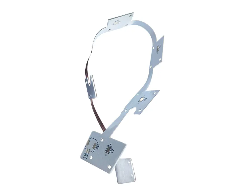
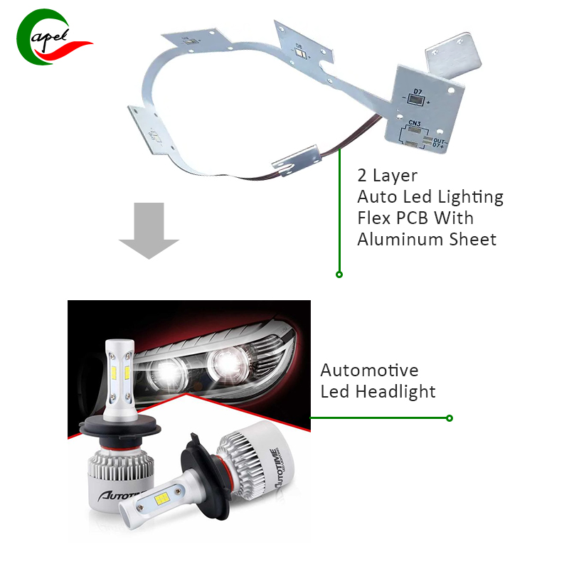
Technical innovation of 2-layer flexible PCB in high-end automotive LED lighting-Capel success case analysis
The line width and line spacing of 0.25mm/0.2mm provide a number of technological innovations for high-end car lights.
First, optimized line width and line spacing mean higher line density and more precise routing, allowing for higher integration and a wider range of functions, such as complex dynamic effects and complex patterns. This provides lighting designers with greater creative potential to develop more attractive and unique designs.
Secondly, the width of 0.25mm/0.2mm means that the PCB has superior flexibility and adaptability. Flexible PCB can more easily adapt to complex car light shapes and structures, providing more design possibilities. This allows the lights to better integrate into the overall appearance of the vehicle, adding a more stylish and unique look to the vehicle.
In addition, optimized line width and line spacing indicate superior circuit performance. Thinner lines can reduce signal transmission losses and improve the stability and reliability of the car lighting system. This enhances the performance of the lighting system, providing faster response times and more reliable brightness control, thereby improving overall safety and convenience.
A plate thickness of 0.2mm +/- 0.03mm is of great technical importance for high-end car lights.
First, this thin flexible PCB design provides a more refined and lightweight design, taking up less space within the headlight and allowing greater design creative freedom. It also helps produce a more streamlined headlight design, improving the aesthetic and technological feel of the overall appearance. In addition, the 0.2mm thick flexible PCB provides excellent thermal management capabilities, which is crucial for high-strength, multi-functional automotive light components, preventing brightness reduction due to heat and extending the service life of the component.
Secondly, the thickness of 0.2mm +/-0.03mm enhances the flexibility and adaptability of the flexible PCB, better adapts to irregular car light designs, achieves changeable dynamic lighting effects, and creates personalized vehicle exterior design and brand aesthetics. Tremendous influence.
The minimum aperture of 0.1mm brings significant technological innovation to high-end car lights.
First, smaller minimum holes can accommodate more components and wires on the PCB, thereby increasing circuit complexity and innovative integration, such as accommodating more LED bulbs, sensors and control circuits to improve smart lighting, brightness control and beam steering to enable innovation. Improve lighting performance and safety.
Second, smaller minimum hole sizes mean more precise circuitry and greater stability. Smaller apertures enable denser, more precise wiring, which is critical for smart upgrades in car lights, as complex functions often require high-speed data transmission and precise signal management.
In addition, the smaller minimum aperture facilitates compact integration of the PCB with other components, ensuring aesthetics while optimizing internal space utilization and overall performance.
ENIG (Electroless Nickel Immersion Gold) surface treatment brings a number of important technological innovations to 2-layer flexible PCBs in high-end automotive lighting applications.
First, the ENIG treatment provides excellent soldering capabilities, ensuring a strong connection and improving the stability and durability of the circuit under adverse conditions such as high temperature, moisture, and vibration.
Additionally, ENIG treatment provides excellent surface flatness and quality. This is crucial for the high-density integration of micro components in high-end car lighting circuits, ensuring precise component placement and welding quality, and improving the reliability and performance of high-end car lighting circuits.
ENIG treatment also provides excellent corrosion resistance, which is critical for high-end automotive lighting circuits exposed to harsh environmental conditions, extending PCB surface life and ensuring circuit stability.
In addition, ENIG treatment provides excellent oxidation resistance, maintains long-term stability for high-end automotive lighting circuits, and improves reliability and durability under demanding requirements.
The ±0.1MM tolerance of 2-layer flexible PCB brings several key technological innovations
Compact design and precise installation: ±0.1MM tolerance means PCBs can be designed more compactly while maintaining precise control. This makes automotive lamp designs more elegant and compact, with better light focusing and scattering effects, and improves overall system reliability and performance.
Material Selection and Thermal Management: Standard tolerances of ±0.1MM allow for the use of a variety of materials in high-end automotive light designs for better thermal management under high temperature, vibration and moisture conditions.
Overall Integrated Design: The tolerance of ±0.1MM allows for an overall integrated design, integrating more functions and components onto a compact PCB, enhancing lighting and overall system performance and reliability.
The material combination of PI (polyimide), copper, adhesive and aluminum in 2-layer flexible PCB brings multiple
technological innovations to high-end automotive lights
High temperature resistance: PI material provides excellent high temperature stability and insulation, meeting the high temperature resistance requirements of high-end car lights. This ensures that the PCB in the car lighting system works stably and reliably under high temperature conditions.
Electrical properties: Copper acts as a good electrical conductor and is suitable for making circuits and solder joints in PCBs. Improve the electrical performance and heat dissipation performance of high-end car lights to ensure stable and reliable circuit operation.
Structural Strength and Flexibility: The use of flexible PI materials and adhesives allows the PCB to adapt to complex vehicle light shapes and installation spaces, allowing for flexible design and reduced overall weight while improving energy efficiency and safety.
Thermal Management: Aluminum has excellent heat transfer properties and can be used for effective heat dissipation in automotive lighting systems. The addition of aluminum to the PCB improves the overall thermal management of the lights, keeping temperatures lower during long periods of high-load operation.
2 Layer Flexible PCB Prototyping and Manufacturing Procee For Automotive Lighting
Summary
The innovative applications of 2-layer flexible PCB technology in the field of high-end automotive lights include line width, line spacing, plate thickness, minimum aperture, surface treatment, size control and material combination. These innovative technologies improve the flexibility, plasticity, performance stability and lighting effects of automobile lights, meet the special needs of automobile lighting systems in terms of high temperature, vibration, and high efficiency, and bring huge benefits to the development of automobiles. Innovations in industrial and automotive products. important driving force.
Post time: Mar-08-2024
Back


