
Date: 2025-07-17
Signal integrity is an important aspect of PCB design, especially for rigid-flex PCBs. These unique circuit boards provide the flexibility and reliability required in today’s advanced electronic devices. However, due to its complex structure, ensuring correct signal integrity in rigid-flex PCB designs can be challenging.
In this blog post, we will discuss the key factors to consider and the steps involved when calculating signal integrity for rigid-flex PCB designs.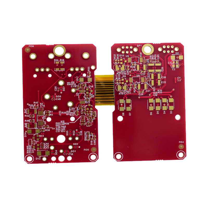
Signal integrity refers to the quality of electrical signals as they pass through a PCB. It involves analyzing and managing various factors that can affect signal performance, such as impedance, noise, crosstalk, and reflections.
For rigid-flex PCBs that combine rigid and flexible substrates, signal integrity becomes even more important. The transition between rigid and flexible sections can introduce impedance changes, signal attenuation, and other signal integrity issues.
The first step in calculating signal integrity is to identify critical signals in a rigid-flex PCB design. These signals are the most sensitive to signal integrity issues and may include high-speed signals, clock signals, power delivery signals, or any other signal critical to the proper operation of the device.
By focusing on critical signals, you can prioritize analysis and mitigation of signal integrity issues.
Impedance control is critical to maintaining signal integrity. It ensures that the impedance of the signal trace matches the characteristic impedance of the transmission line used. In rigid-flex PCBs, impedance changes may occur at the transition point between the rigid and flexible parts.
To calculate impedance and verify its control, you can use an impedance calculator, a simulation tool, or consult the data sheet provided by the PCB manufacturer. By accurately calculating and controlling impedance, signal reflections can be minimized, ensuring better signal transmission.
Simulation is a powerful tool for analyzing signal integrity in PCB designs. By using specialized software, you can simulate the behavior of signals and identify potential signal integrity issues before manufacturing.
Simulation can help you evaluate parameters such as eye diagram, bit error rate, and signal integrity margin. It allows you to test different scenarios, optimize tracerouting, and validate your design choices.
Crosstalk occurs when signals interfere with each other due to electromagnetic coupling between adjacent conductors. In rigid-flex PCBs, managing crosstalk is more challenging due to the close proximity of conductors in the flex area.
To minimize crosstalk, you can use techniques such as increasing the spacing between traces, using ground or power planes as shields, adding isolation materials, or implementing impedance-controlled trace routing.
Differential signaling is an efficient technology for high-speed data transmission. By using two complementary signals of equal amplitude but opposite polarity, it provides noise immunity and reduces the chance of signal degradation.
In rigid-flex PCB designs, implementing differential pairs helps maintain signal integrity and minimize electromagnetic interference. However, care must be taken to ensure balanced impedance and controlled offset between differential pairs.
Design verification is an iterative process that involves repeatedly simulating, analyzing, and testing the PCB design. It helps identify and resolve signal integrity issues at different stages of the design process.
By conducting a series of design reviews, signal integrity simulations, and prototype testing, you can ensure that your rigid-flex PCB design meets the required signal integrity specifications.
Calculating the signal integrity of a rigid-flex PCB design involves understanding its unique challenges, analyzing critical signals, controlling impedance, minimizing crosstalk, and iteratively validating the design. By following these steps and leveraging simulation tools and verification techniques, you can effectively ensure proper signal integrity in rigid-flex PCB designs.
![]()
Kaboer manufacturing PCBs since 2009. Professional technology and high-precision Printed Circuit Boards involved in Medical, IOT, UAV, Aviation, Automotive, Aerospace, Industrial Control, Artificial Intelligence, Consumer Electronics etc..


 English


 Wechat
 +86 13670210335
 +86 13670210335
 E-mail