
If you’ve dabbled in electronics and circuit board design, you’ve probably come across the term “Rigid Flexible Printed Circuit Board”. Rigid-flex PCBs are gaining popularity for their flexibility, durability, and space-saving capabilities. By combining flexible and rigid substrates on a single board, designers can maximize the functionality of their devices while minimizing size constraints. Here in this comprehensive guide, Capel will dive into the basic steps and best practices for designing a rigid-flex PCB. Whether you are a seasoned professional or new to PCB design, this article will provide you with the knowledge and tools you need to successfully create robust and reliable rigid flexible PCBs.
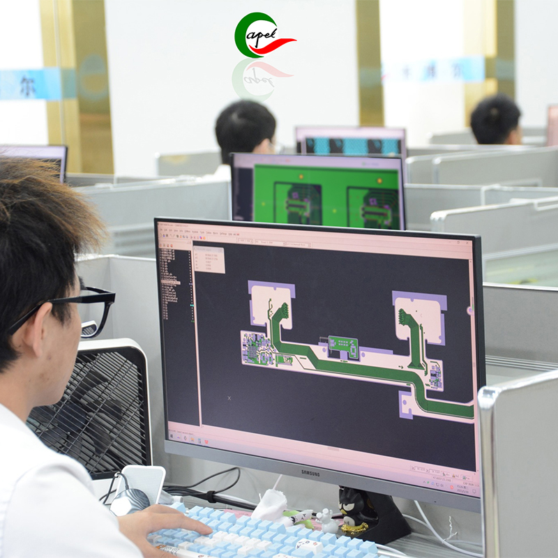
Table of contents:
Understanding Rigid-Flex circuit board
Advantages of rigid-flex PCB board
Design Considerations for Rigid Flexible PCBs
Rigid-flex PCB design process
Tools and Software for Rigid-Flex PCB Design
Testing and Manufacturing Rigid-Flex PCBs
In conclusion
Understanding Pcb Rigid Flex:
Before diving into the design process, it is crucial to have a clear understanding of what a rigid-flex PCB is. A rigid-flex PCB is a hybrid circuit board that combines flexible and rigid substrates into a single structure. By integrating flexible printed circuits with rigid parts, these boards increase reliability, reduce size and increase durability compared to traditional PCBs. The flexible regions allow for 3D configuration, while the rigid parts provide stability and support to the assembly.
Advantages of Rigid Flex Board:
The use of rigid-flex PCBs brings several advantages that make them an attractive choice for many applications. These benefits
include:
Space saving: One of the main advantages of rigid-flex PCBs is their ability to save space. These boards integrate multiple boards into one compact structure by eliminating connectors and wiring. This not only reduces the overall size of the electronic device, but also reduces its weight, making it suitable for compact portable applications.
Enhanced Reliability: Rigid-flex PCBs have higher reliability compared to conventional PCBs. The combination of flexible and rigid substrates provides stability to the assembly, reducing the risk of breakage or failure. The flexible part absorbs mechanical stress and prevents damage from vibration, shock or temperature changes. This enhanced reliability ensures that electronic devices remain functional even under challenging environmental conditions.
Design Flexibility: Rigid Flex Circuit Boards offer unparalleled design flexibility. They support 3D configurations and complex layouts, enabling designers to create innovative and compact solutions for complex electronic devices. This flexibility opens up the possibility of unique and custom designs tailored to specific applications.
Improved Durability: By eliminating connectors and cables, rigid-flex PCBs minimize the risks associated with loose connections or wire fatigue. The absence of moving parts further increases durability because there are fewer points of failure. Additionally, the flexible portion of the PCB has excellent resistance to vibration, shock, and extreme temperature changes, making it suitable for harsh environments.
Cost-effective: While the initial cost of Rigid Flex circuit boards may be slightly higher than traditional rigid PCBs, they can save money in the long run. Elimination of connectors and wiring reduces assembly complexity and time, which reduces labor costs. Additionally, the reliability and durability of rigid-flex boards can reduce maintenance and repair expenses, improving overall cost efficiency in the long run.
Design considerations for rigid flex design guide:
Designing a rigid-flex PCB requires careful consideration of various factors to ensure optimum performance and reliability.
Here are some key design considerations to keep in mind:
a. Mechanical Constraints: Understand and analyze the mechanical constraints of equipment. Determine the required bend area, fold angle, and any connectors or components that may require additional support. Flexible sections are designed to withstand repeated bending and folding without compromising their functionality.
b. Trace Routing: Ensure proper trace routing to maintain signal integrity. Avoid placing traces near bend areas to minimize the risk of short circuits or signal interference. Maintain proper spacing between traces to prevent crosstalk and signal degradation. Consider using impedance-controlled traces for high-speed signals to minimize signal reflections and losses.
c. Component Placement: Optimize component placement to ensure stability and avoid interference with curved areas. Consider component size, weight, and thermal characteristics to prevent stress concentrations in flexible areas. Place heavier components on rigid sections for stability, and avoid placing tall components that might interfere with board bending or folding.
d. Material Selection: Select materials suitable for the flexible and rigid parts of the PCB. Consider flexibility, heat resistance, and compatibility with manufacturing processes. Flexible materials should have good bendability and durability, while rigid materials should have sufficient mechanical strength. Make sure the selected material is compatible with the assembly and soldering process.
e. Copper Balance: Maintains a balanced distribution of copper on the PCB to prevent warping, cracking, or other mechanical failures. Use proper copper thickness and pattern distribution to minimize stress concentrations. Avoid heavy copper traces or high copper density in flex areas to prevent mechanical stress and failure.
F. Design for Manufacturability: Work closely with manufacturers throughout the design process to ensure manufacturability of rigid-flex PCBs. Consider the capabilities and limitations of manufacturing and assembly processes, such as lamination, drilling, and etching. Optimize designs to simplify manufacturing, assembly and testing.
Rigid-flex PCB design process:
Designing a robust rigid-flex PCB involves several critical steps to ensure a successful and reliable design.Here is a step-by-step
guide to the design process:
Define Design Requirements: Start by clearly defining the project’s requirements, including desired functionality, electrical specifications, and mechanical constraints. This will provide a solid foundation for the design process.
Schematic Design: Create circuit schematics to establish electrical connections and component placement. This step helps determine the overall layout of the PCB and ensures that all necessary components are included.
Board shape definition: Determine the overall size and shape of the rigid-flex board. Consider equipment size and any mechanical constraints, such as available space or specific installation requirements.
Component placement: Place components on a rigid portion of the board, ensuring adequate spacing for copper traces. Consider thermal management and avoid placing components that may interfere with flexible parts. This step helps optimize the layout for performance and manufacturability.
Trace Routing: Route copper traces on the board, placing critical signals on as rigid components as possible. Pay close attention to impedance matching, noise management, and avoiding high-speed signal crossings. Follow best practices for signal integrity and consider any specific requirements for rigid-flex designs.
Flexible design: After the rigid wiring is completed, focus on wiring the flexible part of the printed circuit boards. Note the stackup, trace width, and spacing requirements provided by the manufacturer. Make sure the design follows the manufacturer’s flex PCB design guidelines to ensure reliability and durability.
Validate the design: Perform a thorough design check using appropriate software tools. This includes design rule checking (DRC), electrical rule checking (ERC) and signal integrity analysis. Verify that the design meets all requirements and ensures proper functionality.
Generation of manufacturing documents: Generate all necessary manufacturing documents according to the manufacturer’s requirements. This includes creating Gerber files, drill files and assembly drawings. Ensure that manufacturing documents accurately reflect the design and provide all the information required for fabrication and assembly.
Review with Manufacturer: Work closely with your chosen manufacturer to review the design and ensure it meets its manufacturing and assembly capabilities. Work with the manufacturer to resolve any questions or concerns and make necessary adjustments to the design.
Tools and Software for Rigid-Flex PCB Design:
Designing rigid flex circuits requires the use of specialized tools and software to ensure accurate and reliable results. Here are
some popular software tools used in the industry:
a. Altium Designer: Known for its comprehensive design capabilities, Altium Designer offers 3D modeling, design rule checking, signal integrity analysis and a user-friendly interface.
b. Cadence Allegro: Cadence Allegro provides a powerful set of tools for designing rigid-flex PCBs. It provides advanced functionality for routing, high-speed design, and constraint management.
c. Mentor Xpedition: Mentor Xpedition is widely used for complex PCB designs, including rigid-flex PCBs. It provides an extensive component library, comprehensive design rule checking and signal integrity analysis.
d. Eagle PCB: Eagle PCB is a popular choice for beginners and small projects. It offers an intuitive interface, schematic capture and layout editors, and flexible design rule configuration.
e. OrCAD: OrCAD PCB Designer is a versatile software package that supports complete PCB design, including rigid flexible pcb. It provides features such as design for manufacturability (DFM) checking, real-time design feedback, and high-speed routing.
f. SolidWorks: This is a popular mechanical design software that can be used in conjunction with PCB design software to create accurate 3D models of PCB flex components. It allows visualization of the PCB in assembled form and helps identify any potential interference or mounting issues.
g. PADS: PADS is a PCB design software from Mentor Graphics, which provides comprehensive design and simulation functions. It offers features tailored for rigid-flex PCB design, including flexible design rule checking and dynamic 3D visualization.
h. KiCad: KiCad is an open source PCB design software that provides comprehensive design tools for rigid-flex PCB design. It provides an intuitive interface, schematic capture and layout editor capabilities, and supports flexible PCB design and routing.
i. SOLIDWORKS PCB: This software combines mechanical and electrical design capabilities, making it ideal for designing rigid-flex boards. It enables efficient collaboration between mechanical and electrical design teams and ensures precise integration of PCB flex and rigid components.
When choosing a software tool for rigid-flex PCB design, it is important to consider factors such as the complexity of the design, the expertise of the design team, and budget constraints. It is recommended to evaluate the features, functionality and user-friendliness of different tools before making a decision.Shenzhen Capel manufactures rigid flexible circuit boards since 2009.Any question welcome to contact with us.
Testing and Fabricating Semi Rigid Flex PCB:
Once the design is complete, combining testing and manufacturing considerations is critical to the successful implementation
of a rigid-flex PCB. Here are some key steps in the testing and manufacturing process:
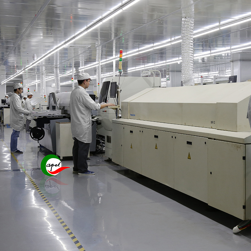
a. Prototype development: A prototype of a rigid-flex PCB design must be created before going into series production. Prototyping enables thorough testing and validation of designs. It helps to spot any design flaws or potential issues early so that necessary modifications can be made.
b. Manufacturing Review: Working closely with the manufacturer, the design is reviewed to ensure it is capable of manufacturing and assembly. Discuss manufacturing recommendations such as material selection, stackup design, and specific requirements for rigid and flexible areas. This step is critical to ensure a smooth manufacturing and assembly process.
c. Design for Testability (DFT): Consider design aspects that enhance the testability of rigid-flex PCBs. Implement features such as test points, access boards, or built-in self-test (BIST) to facilitate testing during manufacturing and throughout the product lifecycle. DFT considerations help simplify the testing process and detect any potential issues.
d. Automated Optical Inspection (AOI): Utilize the AOI system to perform automated optical inspection of the fabricated rigid-flex PCB. AOI systems can detect potential manufacturing defects such as shorts, opens, misaligned components or solder joints. This step ensures the quality and reliability of the manufactured boards.
e. Reliability test: Strict reliability test is carried out on the manufactured rigid-flex board. This testing includes environmental stress testing, thermal cycling, vibration testing and functional testing of the board. Reliability testing verifies the durability and performance of the PCB under real-world conditions.
F. Design Documentation: Maintain comprehensive design documentation including bill of materials (BOM), assembly drawings, test plans and test specifications. This document is essential for troubleshooting, repairs, and future revisions. It can be used as a reference for the entire product life cycle.
By following these steps, Capel pcb manufacturers can ensure successful testing and manufacturing of rigid-flex boards, resulting in high-quality and reliable products.
In Summary:
Designing and manufacturing rigid flexible printed circuit board requires a thorough understanding of the mechanical, electrical, and manufacturing aspects involved. Following the principles outlined in this guide,Capel ensures the successful design, testing, and manufacture of robust and reliable rigid-flex PCBs. Rigid-flex saves space, enhances durability and flexibility, making it a valuable solution in various industries. It is important to stay up-to-date with the latest design tools, materials, and manufacturing processes to fully utilize the potential of rigid-flex PCBs and contribute to electronic design innovation. By implementing these strategies, Capel create creats cutting-edge PCB solutions that meet the ever-changing needs of the electronics industry.
Shenzhen Capel Technology Co., Ltd.established its own Rigid Flex Pcb factory in 2009 and it is a professional Flex Rigid Pcb Manufacturer. With 15 years of rich project experience, rigorous process flow, excellent technical capabilities, advanced automation equipment,comprehensive quality control system, and Capel has a professional experts team to provide global customers with high-precision, high-quality rigid flex board, Hdi Rigid Flex Pcb, Rigid Flex Pcb Fabrication, Fast Turn Rigid Flex Pcb,quick turn pcb prototypes .Our responsive pre-sales and after-sales technical services and timely delivery enable our clients to quickly seize market opportunities for their projects.
Post time: Aug-26-2023
Back


