
EMI (electromagnetic interference) and RFI (radio frequency interference) are common challenges when designing printed circuit boards (PCBs). In rigid-flex PCB design, these issues require special consideration due to the combination of rigid and flexible areas. Here This article will explore various strategies and techniques to ensure effective EMI/RFI shielding in rigid flex board designs to minimize interference and maximize performance.
Understanding EMI and RFI in Rigid Flexible PCB:
What EMI and RFI are:
EMI stands for Electromagnetic Interference and RFI stands for Radio Frequency Interference. Both EMI and RFI refer to the phenomenon in which unwanted electromagnetic signals disrupt the normal function of electronic equipment and systems. These interfering signals can degrade signal quality, distort data transmission, and even cause complete system failure.
How they can adversely affect electronic equipment and systems:
EMI and RFI can adversely affect electronic equipment and systems in a variety of ways. They can disrupt the proper operation of sensitive circuits, causing errors or malfunctions. In digital systems, EMI and RFI can cause data corruption, resulting in errors or loss of information. In analog systems, interfering signals introduce noise that distorts the original signal and degrades the quality of the audio or video output. EMI and RFI can also affect the performance of wireless communication systems, causing reduced range, dropped calls, or lost connections.
Sources of EMI/RFI:
The sources of EMI/RFI are varied and can be caused by external and internal factors. External sources include electromagnetic fields from power lines, electric motors, radio transmitters, radar systems, and lightning strikes. These external sources can generate strong electromagnetic signals that can radiate and couple with nearby electronic equipment, causing interference. Internal sources of EMI/RFI can include components and circuits within the equipment itself. Switching elements, high-speed digital signals, and improper grounding can generate electromagnetic radiation within the device that can interfere with nearby sensitive circuitry.
The Importance of EMI/RFI Shielding in Rigid Flex PCB Design:
The importance of EMI/RFI shielding in rigid pcb board design:
EMI/RFI shielding plays a vital role in PCB design, especially for sensitive electronic equipment such as medical equipment, aerospace systems, and communication equipment. The main reason for implementing EMI/RFI shielding is to protect these devices from the negative effects of electromagnetic and radio frequency interference.
The negative effects of EMI/RFI:
One of the main problems with EMI/RFI is signal attenuation. When electronic equipment is subjected to electromagnetic interference, the quality and integrity of the signal may be affected. This may result in data corruption, communication errors and loss of important information. In sensitive applications such as medical devices and aerospace systems, these signal attenuations can have serious consequences, affecting patient safety or compromising the performance of critical systems;
Equipment failure is another important problem caused by EMI/RFI. Interfering signals can disrupt the normal operation of electronic circuits, causing them to malfunction or fail completely. This can lead to equipment downtime, costly repairs and potential safety hazards. In medical equipment, for example, EMI/RFI interference can cause incorrect readings, incorrect dosing, and even equipment failure during critical processes.
Data loss is another consequence of EMI/RFI interference. In applications such as communications equipment, interference can cause dropped calls, lost connections, or corrupted data transmissions. This can have an adverse impact on communication systems, impacting productivity, business operations and customer satisfaction.
To mitigate these negative effects, EMI/RFI shielding is incorporated into the pcb rigid flex design. Shielding materials such as metal casings, conductive coatings, and shielding cans create a barrier between sensitive electronic components and external sources of interference. The shielding layer acts as a shield to absorb or reflect interference signals, preventing interference signals from penetrating into the rigid flex board, thereby ensuring the integrity and reliability of electronic equipment.
Key Considerations for EMI/RFI Shielding in Rigid Flex PCB Fabrication:
The unique challenges faced in rigid flex circuit boards design:
Rigid-flex PCB designs combine rigid and flex areas, presenting unique challenges for EMI/RFI shielding. The flexible part of the PCB acts as an antenna, transmitting and receiving electromagnetic waves. This increases the susceptibility of sensitive components to electromagnetic interference. Therefore, implementing effective EMI/RFI shielding techniques in quick turn rigid flex pcb designs is critical.
Address the need for proper grounding techniques and shielding strategies:
Proper grounding techniques are critical to isolating sensitive components from electromagnetic interference. Ground planes should be placed strategically to ensure effective grounding of the entire rigid flex circuits. These ground planes act as a shield, providing a low impedance path for EMI/RFI away from sensitive components. Also, using multiple ground planes helps minimize crosstalk and reduce EMI/RFI noise.
Shielding strategies also play a vital role in EMI/RFI prevention. Covering sensitive components or critical parts of the PCB with a conductive shield can help contain and block interference. EMI/RFI shielding materials, such as conductive foils or coatings, can also be applied to rigid-flex circuits or specific areas to provide further protection from external sources of interference.
The importance of layout optimization, component placement, and signal routing:
Layout optimization, component placement, and signal routing are critical to minimizing EMI/RFI issues in rigid-flex PCB designs. Proper layout design ensures that sensitive components are kept away from potential EMI/RFI sources, such as high-frequency circuits or power traces. Signal traces should be routed in a controlled and organized manner to reduce crosstalk and minimize the length of high-speed signal paths. It is also important to maintain proper spacing between traces and keep them away from potential sources of interference. Component placement is another important consideration. Placing sensitive components close to the ground plane helps minimize EMI/RFI coupling. Components that have high emissions or are susceptible should be isolated from other components or sensitive areas as much as possible.
Common EMI/RFI Shielding Techniques:
The advantages and limitations of each technique and their applicability to rigid-flex PCB designs Guidelines:
Proper Enclosure Design: A well-designed enclosure acts as a shield from external EMI/RFI sources. Metal enclosures, such as aluminum or steel, provide excellent shielding. The enclosure should be properly grounded to keep any external interference away from sensitive components. However, in a flex-rigid pcb design, the flex area presents a challenge to achieve proper housing shielding.
Shielding Coating: Applying a shielding coating, such as conductive paint or spray, to the surface of the PCB can help minimize EMI/RFI effects. These coatings consist of metal particles or conductive materials such as carbon, which form a conductive layer that reflects and absorbs electromagnetic waves. Shield coatings can be selectively applied to specific areas prone to EMI/RFI. However, due to its limited flexibility, coatings may not be suitable for flexible areas of rigid-flex boards.
Shielding Can: A shielding can, also known as a Faraday cage, is a metal enclosure that provides localized shielding for a specific component or section of a rigid-flex circuit prototype. These cans can be mounted directly on sensitive components to prevent EMI/RFI interference. Shielded cans are especially effective for high frequency signals. However, using shielding cans in flex areas can be challenging due to their limited flexibility in rigid-flex PCB designs.
Conductive Gaskets: Conductive gaskets are used to seal gaps between housings, covers, and connectors, ensuring a continuous conductive path. They provide EMI/RFI shielding and environmental sealing. Conductive gaskets are usually made of conductive elastomer, metalized fabric or conductive foam. They can be compressed to provide good electrical contact between mating surfaces. Conductive spacers are suitable for rigid-flex PCB designs because they can conform to the bending of the rigid-flex printed circuit board.
How to use shielding materials such as conductive foils, films and paints to minimize EMI/RFI effects:
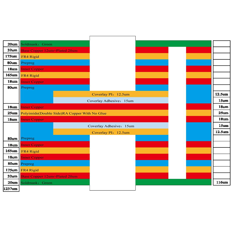
Use shielding materials such as conductive foils, films, and paints to minimize EMI/RFI effects. Conductive foil, such as copper or aluminum foil, can be applied to specific areas of the flex-rigid pcb for localized shielding. Conductive films are thin sheets of conductive material that can be laminated to the surface of a multilayer rigid-flex board or integrated into a Rigid Flex Pcb Stackup. Conductive paint or spray can be selectively applied to areas susceptible to EMI/RFI.
The advantage of these shielding materials is their flexibility, allowing them to conform to the contours of rigid-flex PCBs. However, these materials may have limitations in shielding effectiveness, especially at higher frequencies. Their proper application, such as careful placement and coverage, is critical to ensure effective shielding.
Grounding and Shielding Strategy:
Gain insight into effective grounding techniques:
Grounding Technology: Star Grounding: In star grounding, a center point is used as the ground reference and all ground connections are directly connected to this point. This technology helps prevent ground loops by minimizing potential differences between different components and reducing noise interference. It is commonly used in audio systems and sensitive electronic equipment.
Ground Plane Design: A ground plane is a large conductive layer in a multilayer rigid-flexible pcb that acts as a ground reference. The ground plane provides a low impedance path for return current, helping to control EMI/RFI. A well-designed ground plane should cover the entire rigid-flex printed circuit and be connected to a reliable ground point. It helps minimize ground impedance and reduces the effect of noise on the signal.
The importance of shielding and how to design it:
The importance of shielding: Shielding is the process of enclosing sensitive components or circuits with conductive material to prevent the ingress of electromagnetic fields. It is critical to minimizing EMI/RFI and maintaining signal integrity. Shielding can be achieved through the use of metal enclosures, conductive coatings, shielding cans, or conductive gaskets.
Shield Design:
Enclosure Shielding: Metal enclosures are often used to shield electronic equipment. The enclosure should be properly grounded to provide an effective shielding path and reduce the effects of external EMI/RFI.
Shielding Coating: Conductive coatings such as conductive paint or conductive spray can be applied to the surface of a rigid-flex printed circuit boards or housing to form a conductive layer that reflects or absorbs electromagnetic waves.
Shielding Cans: Shielding cans, also known as Faraday cages, are metal enclosures that provide partial shielding for specific components. They can be mounted directly on sensitive components to prevent EMI/RFI interference.
Conductive Gaskets: Conductive gaskets are used to seal gaps between enclosures, covers, or connectors. They provide EMI/RFI shielding and environmental sealing.
The concept of shielding effectiveness and the selection of suitable shielding materials:
Shielding effectiveness and material selection: Shielding effectiveness measures a material’s ability to attenuate and reflect electromagnetic waves. It is usually expressed in decibels (dB) and indicates the amount of signal attenuation achieved by the shielding material. When selecting a shielding material, it is important to consider its shielding effectiveness, conductivity, flexibility, and compatibility with system requirements.
EMC Design Guidelines:
best practices for EMC (Electromagnetic Compatibility) design guidelines and the importance of complying with EMC industry
standards and regulations:
Minimize loop area: Reducing loop area helps minimize loop inductance, thereby reducing the chance of EMI. This can be achieved by keeping traces short, using a solid ground plane, and avoiding large loops in the circuit layout.
Reduce high-speed signal routing: High-speed signals will generate more electromagnetic radiation, increasing the possibility of interference. To mitigate this, consider implementing controlled impedance traces, using well-designed signal return paths, and using shielding techniques such as differential signaling and impedance matching.
Avoid parallel routing: Parallel routing of signal traces can lead to unintended coupling and crosstalk, which can lead to interference problems. Instead, use vertical or angled trace routing to minimize the proximity between critical signals.
Compliance with EMC Standards and Regulations: Compliance with industry-specific EMC standards, such as those established by the FCC, is critical to ensuring equipment reliability and preventing interference with other equipment. Compliance with these regulations requires thorough testing and verification of equipment for electromagnetic emissions and susceptibility.
Implement grounding and shielding techniques: Proper grounding and shielding techniques are critical to controlling electromagnetic emissions and susceptibility. Always refer to a single ground point, implement a star ground, use a ground plane, and use shielding materials such as conductive enclosures or coatings.
Perform simulation and testing: Simulation tools can help identify potential EMC issues early in the design phase. Thorough testing must also be performed to verify equipment performance and ensure compliance with required EMC standards.
By following these guidelines, designers can enhance the EMC performance of electronic equipment and minimize the risk of electromagnetic interference, ensuring its reliable operation and compatibility with other equipment in the electromagnetic environment.
Testing and Validation:
The importance of testing and verification to ensure effective EMI/RFI shielding in rigid-flex PCB designs:
Testing and verification play a vital role in ensuring the effectiveness of EMI/RFI shielding in rigid-flex PCB designs. Effective shielding is essential to prevent electromagnetic interference and maintain device performance and reliability.
Testing Methods:
Near-field scanning: Near-field scanning is used to measure the radiated emissions of rigid-flex circuits and identify sources of electromagnetic radiation. It helps pinpoint areas that require additional shielding and can be used during the design phase to optimize shield placement.
Full-wave analysis: Full-wave analysis, such as electromagnetic field simulation, is used to calculate the electromagnetic behavior of a flexi rigid pcb design. It provides insight into potential EMI/RFI issues, such as coupling and resonance, and helps optimize shielding techniques.
Susceptibility testing: Susceptibility testing evaluates a device’s ability to withstand external electromagnetic disturbances. It involves exposing a device to a controlled electromagnetic field and evaluating its performance. This testing helps to identify weak points in the shield design and make necessary improvements.
EMI/RFI Compliance Testing: Compliance testing ensures that equipment meets required electromagnetic compatibility standards and regulations. These tests involve evaluating radiated and conducted emissions, and susceptibility to external disturbances. Conformance testing helps verify the effectiveness of shielding measures and ensures the compatibility of equipment with other electronic systems.
Future Developments in EMI/RFI Shielding:
Ongoing research and emerging technologies in the field of EMI/RFI shielding focus on improving performance and efficiency. Nanomaterials such as conductive polymers and carbon nanotubes provide enhanced conductivity and flexibility, allowing shielding materials to be thinner and lighter. Advanced shielding designs, such as multilayer structures with optimized geometries, increase shielding efficiency. In addition, integrating wireless communication functions into shielding materials can monitor the shielding performance in real time and automatically adjust the shielding performance. These developments are aimed at addressing the increasing complexity and density of electronic equipment while ensuring reliable protection against EMI/RFI interference.
Conclusion:
Effective EMI/RFI shielding in rigid flex board designs is critical to ensuring optimum performance and reliability of electronic devices. By understanding the challenges involved and implementing proper shielding techniques, layout optimization, grounding strategies, and adherence to industry standards, designers can mitigate EMI/RFI issues and minimize the risk of interference. Regularly testing, validating, and understanding future developments in EMI/RFI shielding will contribute to a successful PCB design that meets the demands of today’s technology-driven world.
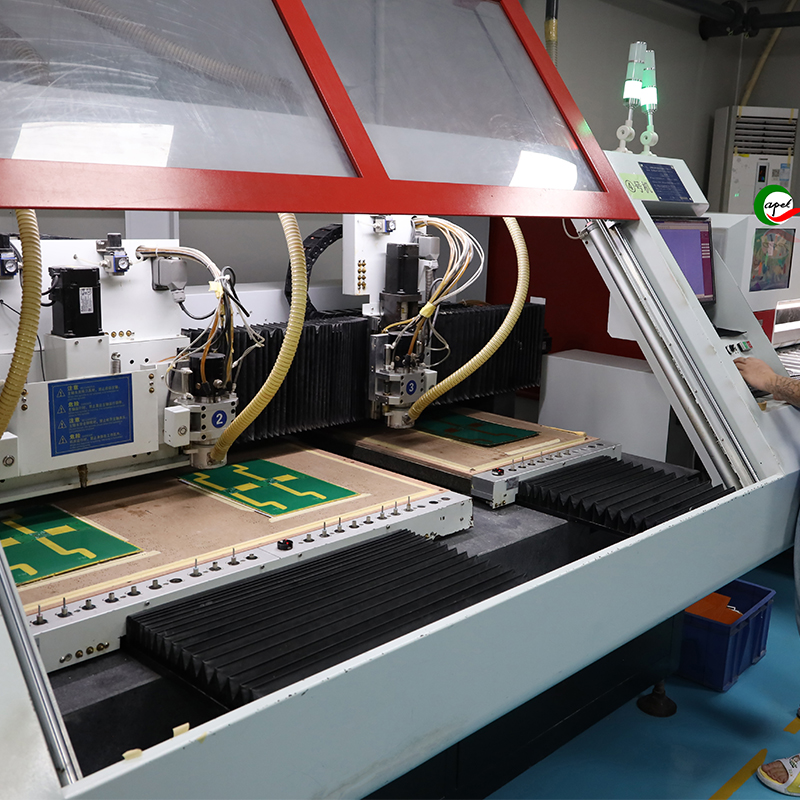
Shenzhen Capel Technology Co., Ltd.established its own Rigid Flex Pcb factory in 2009 and it is a professional Flex Rigid Pcb Manufacturer. With 15 years of rich project experience, rigorous process flow, excellent technical capabilities, advanced automation equipment,comprehensive quality control system, and Capel has a professional experts team to provide global customers with high-precision, high-quality Rigid Flex Rigid Pcb, Rigid Flex Pcb Fabrication, Fast Turn Rigid Flex Pcb,.Our responsive pre-sales and post-sales technical services and timely delivery enable our clients to quickly seize market opportunities for their projects.
Post time: Aug-25-2023
Back


