
PCBA manufacturing is a crucial and complex process that involves assembling various components on a printed circuit board (PCB). However, during this manufacturing process there can be issues with certain components or solder joints sticking, which can lead to potential issues such as poor soldering, damaged components or electrical connection issues. Understanding the reasons behind this phenomenon and finding effective solutions are crucial to ensuring the quality and reliability of the final product. In this article, we will delve into the reasons why these components or solder joints stick during PCBA manufacturing and provide practical and effective solutions to solve this problem. By implementing recommended solutions, manufacturers can overcome this problem and achieve successful PCB assembly with improved soldering, protected components, and stable electrical connections.
1: Understanding the phenomenon in PCB Assembly Manufacturing:
Definition of PCBA Manufacturing:
PCBA manufacturing refers to the process of assembling various electronic components onto a printed circuit board (PCB) to create functional electronic devices. This process involves placing the components onto the PCB and soldering them into place.
The Importance of Proper Component Assembly:
Proper assembly of components is critical to the reliable operation of electronic devices. It ensures that components are securely attached to the PCB and connected correctly, allowing for valid electrical signals and preventing any loose connections.
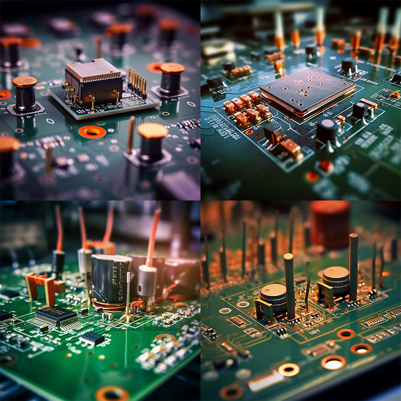
Upright component and solder joint description :
When a component or solder joint is referred to as “straight” in PCBA manufacturing, it means that it is not flat or does not line up properly with the PCB surface. In other words, the component or solder joint is not flush with the PCB.
Potential problems caused by upright components and solder joints:
Upright components and solder joints can cause a number of problems during PCBA manufacturing and operation of the final electronic device. Some potential problems caused by this phenomenon include:
Poor soldering:
Upright solder joints may not make proper contact with the PCB pads, resulting in insufficient solder flow and a weak electrical connection. This reduces the overall reliability and performance of the device.
Mechanical stress:
Upright components may be subject to greater mechanical stress because they are not firmly connected to the PCB surface. This stress can cause components to break or even detach from the PCB, causing the device to malfunction.
Poor electrical connection:
When a component or solder joint stands upright, there is a risk of poor electrical contact. This may result in intermittent connections, loss of signal, or reduced conductivity, affecting the proper operation of the electronic device.
Overheating:
Upright components may not dissipate heat effectively. This can affect the device’s thermal management, causing overheating and potentially damaging components or shortening their service life.
Signal integrity issues:
Standing components or solder joints can cause improper impedance matching between circuits, signal reflections, or crosstalk. These issues can degrade the overall signal integrity and performance of the electronic device.
During the PCBA manufacturing process, timely resolution of upright component and solder joint issues is crucial to ensure the quality, reliability, and longevity of the final product.
2.Reasons why components or solder joints stand upright in PCBA Manufacturing Process:
Uneven temperature distribution: Uneven heating, cooling, or temperature distribution on the PCB can cause components or solder joints to stand up. During the soldering process, if certain areas on the PCB receive more or less heat than others, this can cause thermal stress on components and solder joints. This thermal stress can cause the solder joints to warp or bend, causing the component to stand upright.One of the common causes of uneven temperature distribution is poor heat transfer during welding. If heat is not evenly distributed on the PCB, some areas may experience higher temperatures while other areas remain cooler. This can be caused by improper placement or distribution of heating elements, insufficient heat transfer media, or inefficient heating technology.
Another factor that causes uneven temperature distribution is improper cooling. If the PCB cools unevenly after the soldering process, some areas may cool faster than others. This rapid cooling can cause thermal shrinkage, causing components or solder joints to stand upright.
Welding process parameters are incorrect: Inaccurate settings such as temperature, time or pressure during soldering can also cause components or solder joints to stand upright. Soldering involves heating to melt the solder and form a strong bond between the component and the PCB. If the temperature is set too high during soldering, it may cause the solder to melt excessively. This can cause excessive solder joint flow and cause components to stand upright. Likewise, insufficient temperature can result in insufficient melting of the solder, resulting in a weak or incomplete joint. Time and pressure settings during the welding process also play a vital role. Insufficient time or pressure may result in incomplete or weak solder joints, which may cause the component to stand. Additionally, excessive pressure during soldering can cause excessive solder flow, causing components to tilt or lift.
Improper component placement: Improper component placement is a common cause of components or solder joints standing upright. During assembly, if components are misaligned or tilted, this can cause uneven solder joint formation. When soldering such components, the solder may not flow evenly, causing the component to stand up. Component misalignment may occur due to human error or malfunction of the automatic placement machine. Accurate and precise component placement must be ensured to avoid such problems. Manufacturers should carefully follow component placement guidelines provided by PCB design or assembly specifications. Poor welding materials or techniques: The quality of the soldering materials and techniques used can significantly affect the formation of solder joints and thus the stability of the component. Low-quality soldering materials may contain impurities, have inconsistent melting points, or contain insufficient flux. Use of such materials may result in weak or defective solder joints that may cause the assembly to stand up.
Improper soldering techniques such as too much or not enough solder paste, uneven or inconsistent reflow, or incorrect temperature distribution can also cause this problem. It is critical to follow proper soldering techniques and guidelines recommended by component manufacturers or industry standards to ensure reliable solder joint formation.
Additionally, inadequate PCB cleaning after soldering can result in residue buildup on solder joints. This residue can cause surface tension issues during reflow, causing components to stand upright.
3. Solutions to solve problems:
Adjust processing temperature: To optimize temperature distribution during welding, consider the following techniques:
Adjust heating equipment: Make sure the heating equipment (such as a hot air or infrared reflow oven) is properly calibrated and provides even heat on the PCB. Check for hot or cold spots and make any necessary adjustments or repairs to ensure consistent temperature distribution.
Implement a preheating step: Preheating the PCB before soldering helps reduce thermal stress and promotes a more even temperature distribution. Preheating can be accomplished using a dedicated preheat station or by gradually raising the temperature in the soldering furnace to achieve even heat transfer.
Optimize welding process parameters: Fine-tuning the welding process parameters is critical to achieving a reliable connection and preventing components from standing upright. Pay attention to the following factors:
Temperature: Set the welding temperature according to the specific requirements of components and welding materials. Follow the guidelines or industry standards provided by the component manufacturer. Avoid temperatures that are too high, which can cause excessive solder flow, and insufficient temperatures, which can cause brittle solder joints.
Time: Make sure the soldering process provides enough time for the solder to melt and form a strong bond. Too short a time can result in weak or incomplete solder joints, while too long a heating time can cause excessive solder flow.
Pressure: Adjust the pressure applied when soldering to avoid over- or under-soldering. Follow the recommended pressure guidelines provided by the component manufacturer or welding equipment supplier.
Ensure correct component placement: Accurate and aligned component placement is critical to avoid standing issues. Consider the following steps:
Use quality placement equipment: Invest in high-quality automated component placement equipment that can accurately position components. Calibrate and maintain equipment regularly to ensure accurate placement.
Verify component orientation: Double-check component orientation before placement. Improper orientation of components can cause misalignment during welding and cause standing problems.
Alignment and Stability: Make sure components are square and securely placed on the PCB pads before soldering. Use alignment devices or clamps to hold the components in place during the welding process to prevent any tilting or movement.
Choose high-quality welding materials: The choice of welding materials significantly affects the quality of the solder joint. Please consider the following guidelines:
Solder alloy: Choose a solder alloy that is suitable for the specific soldering process, components and PCB materials used. Use alloys with consistent melting points and good wetting properties for reliable welding.
Flux: Use a high-quality flux appropriate for the soldering process and PCB material used. The flux should promote good wetting and provide adequate cleaning of the solder surface.
Solder Paste: Make sure the solder paste used has the correct composition and particle size distribution to achieve proper melting and flow characteristics. Different solder paste formulations are available for various soldering techniques, such as reflow or wave soldering.
Keep your PCB clean: A clean PCB surface is essential for high-quality soldering. Please follow these steps to keep your PCB clean:
Flux Residue Removal: Completely remove flux residue from PCB after soldering. Use a suitable cleaner, such as isopropyl alcohol (IPA) or a specialized flux remover, to remove any flux residue that may interfere with solder joint formation or cause surface tension issues.
Contaminant Removal: Remove all contaminants such as dirt, dust or oil from the PCB surface before soldering. Use a lint-free rag or brush to gently clean the PCB surface to avoid damaging delicate components.
Storage and Handling: Store and handle PCBs in a clean, dust-free environment. Use protective covers or bags to prevent contamination during storage and transportation. Regularly inspect and monitor PCB cleanliness and establish appropriate process controls to maintain consistent cleanliness levels.
4.The importance of professional assistance in PCBA Manufacturing:
When dealing with complex issues related to stand-up components or solder joints during PCB assembly, it is critical to seek professional help from an experienced manufacturer. Professional PCB assembly manufacturer Capel offers a variety of advantages that can help troubleshoot and resolve these issues effectively.
experience: Professional PCB assembly manufacturer Capel has 15 years of experience in solving various PCB assembly challenges. They encountered and successfully resolved a variety of issues, including upright assembly and solder joint issues. Their experience allows them to quickly identify the root causes of these issues and implement appropriate solutions. With knowledge gained from countless projects, they can provide valuable insights and advice to ensure PCB assembly success.
Expertise: Capel employ highly skilled and well-trained PCB assembly technicians. These technicians possess in-depth knowledge of soldering techniques, component placement and quality control measures. They understand the intricacies of the assembly process and are well-versed in industry standards and best practices. Our expertise allows us to conduct meticulous inspections, identify potential risks, and make necessary adjustments to overcome upright component or solder joint issues. By leveraging our expertise, professional PCB assembly manufacturer Capel can ensure the highest assembly quality and reduce the likelihood of future problems.
Advanced equipment: Professional PCB assembly manufacturer Capel invest in state-of-the-art equipment and technology to enhance soldering and assembly processes. They utilize advanced reflow ovens, automated component placement machines and inspection tools to obtain precise and reliable results. These machines are carefully calibrated and maintained to ensure precise temperature control, precise component placement, and thorough inspection of solder joints. By utilizing advanced equipment, Capel can eliminate many common causes of stand-up assembly or solder joint problems, such as temperature changes, misalignment, or poor solder flow.
QC: Professional PCB assembly manufacturer Capel has complete quality control measures to ensure the highest level of product quality and reliability. They follow strict quality control processes throughout the entire assembly process, from component procurement to final inspection. This includes a thorough inspection of components, solder joints and PCB cleanliness. We have rigorous testing procedures such as X-ray inspection and automated optical inspection to detect any potential defects or anomalies. By adhering to strict quality control measures, professional manufacturers can minimize the occurrence of upright component or solder joint problems and provide reliable PCB assemblies.
Cost and time efficiency: Work with a professional PCB assembly manufacturer Capel can save time and costs. Their expertise and advanced equipment can quickly identify and resolve stand-up component or solder joint issues, minimizing potential delays in production schedules. Additionally, the risk of costly rework or scrapping of defective components can be significantly reduced when working with professionals who have the necessary knowledge and experience. This can save costs in the long run.
In summary, the presence of upstanding components or solder joints during PCBA manufacturing can cause serious problems. By understanding the reasons behind this phenomenon and implementing appropriate solutions, manufacturers can improve weld quality, prevent component damage, and ensure reliable electrical connections. Working with a professional PCB assembly manufacturer Capel can also provide the necessary support and expertise to solve this problem. By following these guidelines, manufacturers can optimize their PCBA manufacturing processes and provide customers with high-quality products.
Post time: Sep-11-2023
Back


