
When FPC flexible circuit board is bent, the stress types on both sides of the core line are different.
This is due to the different forces acting on the inside and outside of the curved surface.
On the inner side of the curved surface, the FPC is subjected to compressive stress. This is because the material is compressed and squeezed as it bends inwards. This compression can cause the layers within the FPC to be compressed, potentially causing delamination or cracking of the component.
On the outside of the curved surface, the FPC is subjected to tensile stress. This is because the material is stretched when it is bent outward. Copper traces and conductive elements on external surfaces may be subjected to tension that may compromise the integrity of the circuit. To relieve the stress on the FPC during bending, it is important to design the flex circuit using proper materials and fabrication techniques. This includes using materials with appropriate flexibility, appropriate thickness, and considering the minimum bend radius of the FPC. Sufficient reinforcement or support structures can also be implemented to distribute stress more evenly across the circuit.
By understanding the types of stress and taking proper design considerations, the reliability and durability of FPC flexible circuit boards when bent or flexed can be improved.
The following are some specific design considerations that can help improve the reliability and durability of FPC flexible circuit boards when they are bent or flexed:
Material Selection: Choosing the right material is critical. A flexible substrate with good flexibility and mechanical strength should be used. Flexible polyimide (PI) is a common choice due to its excellent thermal stability and flexibility.
Circuit Layout: Proper circuit layout is important to ensure that conductive traces and components are placed and routed in a manner that minimizes stress concentrations during bending. It is recommended to use rounded corners instead of sharp corners.
Reinforcement and Support Structures: Adding reinforcement or support structures along critical bending areas can help distribute stress more evenly and prevent damage or delamination. Reinforcement layers or ribs can be applied to specific areas to improve overall mechanical integrity.
Bending Radius: Minimum bending radii should be defined and considered during the design phase. Exceeding the minimum bend radius will result in excessive stress concentrations and failure.
Protection and Encapsulation: Protection such as conformal coatings or encapsulation materials can provide additional mechanical strength and protect circuits from environmental elements such as moisture, dust, and chemicals.
Testing and Validation: Conducting comprehensive testing and validation, including mechanical bend and flex tests, can help evaluate the reliability and durability of FPC flexible circuit boards under real-world conditions.
The inside of the curved surface is pressure, and the outside is tensile. The magnitude of stress is related to the thickness and bending radius of FPC flexible circuit board. Excessive stress will make FPC flexible circuit board lamination, copper foil fracture and so on. Therefore, the lamination structure of FPC flexible circuit board should be reasonably arranged in the design, so that the two ends of the center line of the curved surface should be symmetrical as far as possible. At the same time, the minimum bending radius should be calculated according to different application situations.
Situation 1. The minimum bending of a single-sided FPC flexible circuit board is shown in the following figure:
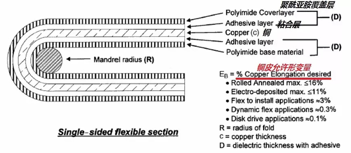
Its minimum bending radius can be calculated by the following formula: R= (c/2) [(100-Eb) /Eb]-D
The minimum bending radius of R=, the thickness of c= copper skin (unit m), the thickness of the D= covering film (m), the permissible deformation of the EB= copper skin (measured by percentage).
The deformation of copper skin varies with different types of copper.
The maximum deformation of A and pressed copper is less than 16%.
The maximum deformation of B and electrolytic copper is less than 11%.
Moreover, the copper content of the same material is also different in different usage occasions. For a one-off bending occasion, the limit value of the critical state of fracture is used (the value is 16%). For the bending installation design, use the minimum deformation value specified by IPC-MF-150 (for the rolled copper, the value is 10%). For dynamic flexible applications, the deformation of copper skin is 0.3%. For the application of magnetic head, the deformation of copper skin is 0.1%. By setting the allowable deformation of the copper skin, the minimum radius of curvature can be calculated.
Dynamic flexibility: the scene of this copper skin application is realized by deformation. For example, the phosphor bullet in the IC card is the part of the IC card inserted into the chip after the insertion of the IC card. In the process of insertion, the shell is deformed continuously. This application scene is flexible and dynamic.
The minimum bending radius of a single-sided flexible PCB depends on several factors, including the material used, the thickness of the board, and the specific requirements of the application. Generally, the bendable radius of the flex circuit board is about 10 times the thickness of the board. For example, if the thickness of the board is 0.1mm, the minimum bending radius is about 1mm. It is important to note that bending the board below the minimum bend radius may result in stress concentrations, strain on the conductive traces, and possibly cracking or delamination of the board. To maintain the electrical and mechanical integrity of the circuit, it is critical to adhere to the recommended bend radii. It is recommended to consult the manufacturer or supplier of the flexible board for specific bending radius guidelines and to ensure that the design and application requirements are met. Additionally, performing mechanical testing and validation can help determine the maximum stress a board can withstand without compromising its functionality and reliability.
Situation 2, double-sided board of FPC flexible circuit board as follow:
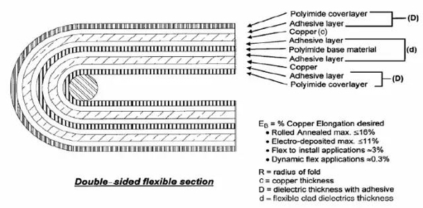
Among them: R= minimum bending radius, unit m, c= copper skin thickness, unit m, D= coverage film thickness, unit m m, EB= copper skin deformation, measured by percentage.
The value of EB is the same as that above.
D= interlayer medium thickness, unit M
The minimum bending radius of a double-sided FPC (Flexible Printed Circuit) flexible circuit board is usually greater than that of a single-sided panel. This is because double-sided panels have conductive traces on both sides, which are more susceptible to stress and strain during bending. The minimum bending radius of a double-sided FPC flex pcb baord is usually about 20 times the thickness of the board. Using the same example as before, if the plate is 0.1mm thick, the minimum bend radius is about 2mm. It is very important to follow the manufacturer’s guidelines and specifications for bending double-sided FPC pcb boards. Exceeding the recommended bend radius may damage conductive traces, cause layer delamination, or cause other problems that affect circuit functionality and reliability. It is recommended to consult the manufacturer or supplier for specific bend radius guidelines, and to perform mechanical testing and verification to ensure that the board can withstand the required bends without compromising its performance.
Post time: Jun-12-2023
Back


