
Date: 2025-07-17
Flexible PCB (Printed Circuit Board) has become more and more popular and widely used in various industries. From consumer electronics to automotive applications, fpc PCB brings enhanced functionality and durability to electronic devices. However, understanding the flexible PCB manufacturing process is critical to ensuring its quality and reliability. In this blog post, we’ll explore the flex PCB manufacturing process in detail, covering each of the key steps involved.
The first step in the flex circuit board manufacturing process is the design and layout phase. At this point, the schematic diagram and component layout are complete. Design software tools such as Altium Designer and Cadence Allegro ensure accuracy and efficiency at this stage. Design requirements such as size, shape and function must be considered to accommodate PCB flexibility.
During the design and layout phase of flex PCB board manufacturing, several steps need to be followed to ensure an accurate and efficient design. These steps include:
Schematic:
Create a schematic to illustrate the electrical connections and function of a circuit. It serves as the basis for the entire design process.
Component placement:
After the schematic is complete, the next step is to determine the placement of the components on the printed circuit board. Factors such as signal integrity, thermal management, and mechanical constraints are considered during component placement.
Routing:
After the components are placed, the printed circuit traces are routed to establish electrical connections between the components. At this stage, the flexibility requirements of the flex circuit PCB should be considered. Special routing techniques such as meander or serpentine routing can be used to accommodate circuit board bends and flex.
Design rule checking:
Before a design is finalized, design rule checking (DRC) is performed to ensure that the design meets specific manufacturing requirements. This includes checking for electrical errors, minimum trace width and spacing, and other design constraints.
Gerber file generation:
After the design is completed, the design file is converted into a Gerber file, which contains the manufacturing information required to produce the flex printed circuit board. These files include layer information, component placement and routing details.
Design Verification:
Designs can be verified through simulation and prototyping before entering the manufacturing phase. This helps identify any potential issues or improvements that need to be made prior to production.
Design software tools such as Altium Designer and Cadence Allegro help simplify the design process by providing features such as schematic capture, component placement, routing and design rule checking. These tools ensure accuracy and efficiency in fpc flexible printed circuit design.
Choosing the right material is critical to the successful manufacture of flexible PCBs. Commonly used materials include flexible polymers, copper foil, and adhesives. Selection depends on factors such as intended application, flexibility requirements, and temperature resistance. Thorough research and collaboration with material suppliers ensures that the best material is selected for a particular project.
Here are some factors to consider when choosing a material:
Flexibility requirements:
The selected material should have the required flexibility to meet specific application needs. There are different types of flexible polymers available, such as polyimide (PI) and polyester (PET), each with varying degrees of flexibility.
Temperature Resistance:
The material should be able to withstand the application’s operating temperature range without deformation or degradation. Different flexible substrates have different maximum temperature ratings, so it is important to choose a material that can handle the required temperature conditions.
Electrical properties:
Materials should have good electrical properties, such as low dielectric constant and low loss tangent, to ensure optimal signal integrity. Copper foil is often used as a conductor in fpc flexible circuit because of its excellent electrical conductivity.
Mechanical Properties:
The material selected should have good mechanical strength and be able to withstand bending and flexing without cracking or cracking. Adhesives used to bond the layers of a flexpcb should also have good mechanical properties to ensure stability and durability.
Compatibility with manufacturing processes:
The selected material should be compatible with the manufacturing processes involved, such as lamination, etching, and welding. It is important to consider material compatibility with these processes to ensure successful manufacturing results.
By considering these factors and working with material suppliers, suitable materials can be selected to meet the flexibility, temperature resistance, electrical performance, mechanical performance, and compatibility requirements of a flex PCB project.
During the substrate preparation phase, the flexible film serves as the basis for the PCB. And during the substrate preparation phase of flex circuit fabrication, it is often necessary to clean the flexible film to ensure that it is free of impurities or residues that may affect the performance of the PCB. The cleaning process typically involves the use of a combination of chemical and mechanical methods to remove contaminants. This step is very important to ensure proper adhesion and bonding of subsequent layers.
After cleaning, the flexible film is coated with an adhesive material that bonds the layers together. The adhesive material used is usually a special adhesive film or liquid adhesive, which is evenly coated on the surface of the flexible film. Adhesives help provide structural integrity and reliability to PCB flex by firmly bonding the layers together.
Adhesive material selection is critical to ensuring proper bonding and meeting the specific requirements of the application. Factors such as bond strength, temperature resistance, flexibility, and compatibility with other materials used in the PCB assembly process need to be considered when selecting an adhesive material.
After the adhesive is applied, the flexible film can be further processed for subsequent layers, such as adding copper foil as conductive traces, adding dielectric layers or connecting components. Adhesives act as glue throughout the manufacturing process to create a stable and reliable flexible PCBs structure.
After preparing the substrate, the next step is to add a layer of copper. This is achieved by laminating copper foil to a flexible film using heat and pressure. The copper layer acts as a conductive path for electrical signals within the flex PCB.
The thickness and quality of the copper layer are key factors in determining the performance and durability of a flexible PCB. Thickness is usually measured in ounces per square foot (oz/ft²), with options ranging from 0.5 oz/ft² to 4 oz/ft². The choice of copper thickness depends on the requirements of the circuit design and the desired electrical performance.
Thicker copper layers provide lower resistance and better current-carrying capability, making them suitable for high-power applications. On the other hand, thinner copper layers provide flexibility and are preferred for applications that require bending or flexing the printed circuit.
Ensuring the quality of the copper layer is also important, as any defects or impurities can affect the electrical performance and reliability of the flex board PCB. Common quality considerations include uniformity of copper layer thickness, absence of pinholes or voids, and proper adhesion to the substrate. Ensuring these quality aspects can help achieve the best performance and longevity of your flex PCB.
At this stage, the desired circuit pattern is formed by etching away excess copper using a chemical etchant. Photoresist is applied to the copper surface, followed by UV exposure and development. The etching process removes unwanted copper, leaving the desired circuit traces, pads, and vias.
Here is a more detailed description of the process:
Application of photoresist:
A thin layer of photosensitive material (called photoresist) is applied to the copper surface. Photoresists are typically coated using a process called spin coating, in which the substrate is rotated at high speeds to ensure uniform coating.
Exposure to UV light:
A photomask containing the desired circuit pattern is placed on the photoresist-coated copper surface. The substrate is then exposed to ultraviolet (UV) light. UV light passes through the transparent areas of the photomask while being blocked by the opaque areas. Exposure to UV light selectively changes the chemical properties of the photoresist, depending on whether it is a positive-tone or negative-tone resist.
Developing:
After exposure to UV light, the photoresist is developed using a chemical solution. Positive-tone photoresists are soluble in developers, while negative-tone photoresists are insoluble. This process removes unwanted photoresist from the copper surface, leaving the desired circuit pattern.
Etching:
Once the remaining photoresist defines the circuit pattern, the next step is to etch away the excess copper. A chemical etchant (usually an acidic solution) is used to dissolve exposed copper areas. The etchant removes the copper and leaves the circuit traces, pads and vias defined by the photoresist.
Photoresist removal:
After etching, the remaining photoresist is removed from the flex PCB. This step is typically performed using a stripping solution that dissolves the photoresist, leaving only the copper circuit pattern.
Inspection and Quality Control:
Finally, the flexible printed circuit board is thoroughly inspected to ensure the accuracy of the circuit pattern and detect any defects. This is an important step in ensuring the quality and reliability of flex PCBs.
By performing these steps, the desired circuit pattern is successfully formed on the flexible PCB, laying the foundation for the next stage of assembly and production.
Solder mask is used to protect circuits and prevent solder bridges during assembly. It is then screen printed to add the necessary labels, logos and component designators for additional functionality and identification purposes.
The following is the process introduction of solder mask and screen printing:
Solder Mask:
Application of Solder Mask:
Solder mask is a protective layer applied to the exposed copper circuit on the flexible PCB. It is usually applied using a process called screen printing. Solder mask ink, usually green in color, is screen printed onto the PCB and covers the copper traces, pads and vias, exposing only the required areas.
Curing and drying:
After the solder mask is applied, the flexible PCB will go through a curing and drying process. The electronic PCB typically passes through a conveyor oven where the solder mask is heated to cure and harden. This ensures that the solder mask provides effective protection and insulation for the circuit.
Open Pad Areas:
In some cases, specific areas of the solder mask are left open to expose copper pads for component soldering. These pad areas are often referred to as Solder Mask Open (SMO) or Solder Mask Defined (SMD) pads. This allows for easy soldering and ensures a secure connection between the component and the PCB circuit board.
screen printing:
Preparation of artwork:
Before screen printing, create artwork that includes labels, logos, and component indicators required for the flex PCB board. This artwork is usually done using computer-aided design (CAD) software.
Screen preparation:
Use artwork to create templates or screens. Areas that need to be printed remain open while the rest are blocked. This is usually done by coating the screen with a photosensitive emulsion and exposing it to UV rays using artwork.
Ink Application:
After preparing the screen, apply the ink to the screen and use a squeegee to spread the ink over the open areas. The ink passes through the open area and is deposited onto the solder mask, adding the desired labels, logos and component indicators.
Drying and curing:
After screen printing, the flex PCB goes through a drying and curing process to ensure that the ink adheres properly to the solder mask surface. This can be achieved by allowing the ink to air dry or using heat or UV light to cure and harden the ink.
The combination of soldermask and silkscreen provides protection for the circuitry and adds a visual identity element for easier assembly and identification of components on the flex PCB.
In the component assembly stage, electronic components are placed and soldered onto the flexible printed circuit board. This can be done through manual or automated processes, depending on the scale of production. Component placement has been carefully considered to ensure optimum performance and minimize stress on the flex PCB.
Following are the main steps involved in component assembly:
Component selection:
Select appropriate electronic components according to circuit design and functional requirements. These elements may include resistors, capacitors, integrated circuits, connectors, and the like.
Component Preparation:
Each component is being prepared for placement, making sure the leads or pads are properly trimmed, straightened and cleaned (if necessary). Surface mount components may come in reel or tray form, while through hole components may come in bulk packaging.
Component placement:
Depending on the scale of production, components are placed on the flexible PCB manually or using automated equipment. Automatic component placement is typically performed using a pick-and-place machine, which precisely positions components onto the correct pads or solder paste on the flex PCB.
Soldering:
Once the components are in place, a soldering process is performed to permanently attach the components to the flex PCB. This is typically done using reflow soldering for surface mount components and wave or hand soldering for through hole components.
Reflow Soldering:
In reflow soldering, the entire PCB is heated to a specific temperature using a reflow oven or similar method. Solder paste applied to the appropriate pad melts and creates a bond between the component lead and the PCB pad, creating a strong electrical and mechanical connection.
Wave Soldering:
For through-hole components, wave soldering is usually used. The flexible printed circuit board is passed through a wave of molten solder, which wets the exposed leads and creates a connection between the component and the printed circuit board.
Hand Soldering:
In some cases, some components may require hand soldering. A skilled technician uses a soldering iron to create solder joints between the components and the flex PCB. Inspection and Testing:
After soldering, the assembled flex PCB is inspected to ensure that all components are soldered correctly and that there are no defects such as solder bridges, open circuits, or misaligned components. Functional testing can also be performed to verify correct operation of the assembled circuit.
To ensure the reliability and functionality of flexible PCBs, testing and inspection are essential. Various techniques such as Automated Optical Inspection (AOI) and In-Circuit Testing (ICT) help identify potential defects, shorts or opens. This step ensures that only high-quality PCBs enter the production process.
The following techniques are commonly used at this stage:
Automated Optical Inspection (AOI):
AOI systems use cameras and image processing algorithms to inspect flexible PCBs for defects. They can detect issues such as component misalignment, missing components, solder joint defects such as solder bridges or insufficient solder, and other visual defects. AOI is a fast and effective PCB inspection method.
In-Circuit Testing (ICT):
ICT is used to test the electrical connectivity and functionality of flexible PCBs. This test involves applying test probes to specific points on the PCB and measuring electrical parameters to check for shorts, opens and component functionality. ICT is often used in high-volume production to quickly identify any electrical faults.
Functional testing:
In addition to ICT, functional testing can also be performed to ensure that the assembled flex PCB performs its intended function correctly. This may involve applying power to the PCB and verifying the circuit’s output and response using test equipment or a dedicated test fixture.
Electrical testing and continuity testing:
Electrical testing involves measuring electrical parameters such as resistance, capacitance, and voltage to ensure proper electrical connections on the flex PCB. Continuity testing checks for opens or shorts that could affect PCB functionality.
By utilizing these testing and inspection techniques, manufacturers can identify and correct any defects or failures in flex PCBs before they enter the production process. This helps ensure that only high-quality PCBs are delivered to customers, improving reliability and performance.
Once the flexible printed circuit board has passed the testing and inspection stage, it goes through a final cleaning process to remove any residue or contamination. The flex PCB is then cut into individual units, ready for packaging. Proper packaging is essential to protect the PCB during shipping and handling.
Here are some key points to consider:
Anti-static packaging:
Since flexible PCBs are susceptible to damage from electrostatic discharge (ESD), they should be packaged with anti-static materials. Antistatic bags or trays made of conductive materials are often used to protect PCBs from static electricity. These materials prevent the build-up and discharge of static charges that can damage components or circuits on the PCB.
Moisture Protection:
Moisture can adversely affect the performance of flex PCBs, especially if they have exposed metal traces or components that are moisture sensitive. Packaging materials that provide a moisture barrier, such as moisture barrier bags or desiccant packs, help prevent moisture penetration during shipping or storage.
Cushioning and shock absorption:
Flexible PCBs are relatively fragile and can easily be damaged by rough handling, impact or vibration during transportation. Packaging materials such as bubble wrap, foam inserts, or foam strips can provide cushioning and shock absorption to protect the PCB from such potential damage.
Proper Labeling:
It is important to have relevant information such as product name, quantity, date of manufacture and any handling instructions on the packaging. This helps ensure proper identification, handling and storage of PCBs.
Secure Packaging:
In order to prevent any movement or displacement of the PCBs inside the package during shipping, they must be properly secured. Inner packing materials such as tape, dividers, or other fixtures can help hold the PCB in place and prevent damage from movement.
By following these packaging practices, manufacturers can ensure that flexible PCBs are well protected and arrive at their destination in a safe and complete condition, ready for installation or further assembly.
Before shipping flex PCBs to customers or assembly plants, we implement strict quality control measures to ensure compliance with industry standards. This includes extensive documentation, traceability and compliance with customer-specific requirements. Adherence to these quality control processes ensures that customers receive reliable and high-quality flexible PCBs.
Here are some additional details about quality control and shipping:
Documentation:
We maintain comprehensive documentation throughout the manufacturing process, including all specifications, design files and inspection records. This documentation ensures traceability and enables us to identify any problems or deviations that may have occurred during production.
Traceability:
Each flex PCB is assigned a unique identifier, allowing us to track its entire journey from raw material to final shipment. This traceability ensures that any potential issues can be quickly resolved and isolated. It also facilitates product recalls or investigations if necessary.
Compliance with customer-specific requirements:
We actively work with our customers to understand their unique requirements and ensure our quality control processes meet their requirements. This includes factors such as specific performance standards, packaging and labeling requirements, and any necessary certifications or standards.
Inspection and Testing:
We conduct thorough inspection and testing at all stages of the manufacturing process to verify the quality and functionality of the flexible printed circuit boards. This includes visual inspection, electrical testing and other specialized measures to detect any defects such as opens, shorts or soldering issues.
Packaging and Shipping:
Once the flex PCBs have passed all quality control measures, we pack them carefully using appropriate materials, as previously mentioned. We also ensure that the packaging is properly labeled with relevant information to ensure proper handling and prevent any mishandling or confusion during shipping.
Shipping Methods and Partners:
We work with reputable shipping partners who are experienced in handling delicate electronic components. We choose the most suitable shipping method based on factors such as speed, cost and destination. Additionally, we track and monitor shipments to ensure they are delivered within the expected timeframe.
By strictly adhering to these quality control measures, we can guarantee that our customers receive a reliable and highest quality flexible PCB that meets their requirements.
In summary, understanding the flexible PCB manufacturing process is critical for both manufacturers and end users. By following meticulous design, material selection, substrate preparation, circuit patterning, assembly, testing, and packaging methods, manufacturers can produce flex PCBs that meet the highest quality standards. As a key component of modern electronic devices, flexible circuit boards can foster innovation and bring enhanced functionality to various industries.
![]()
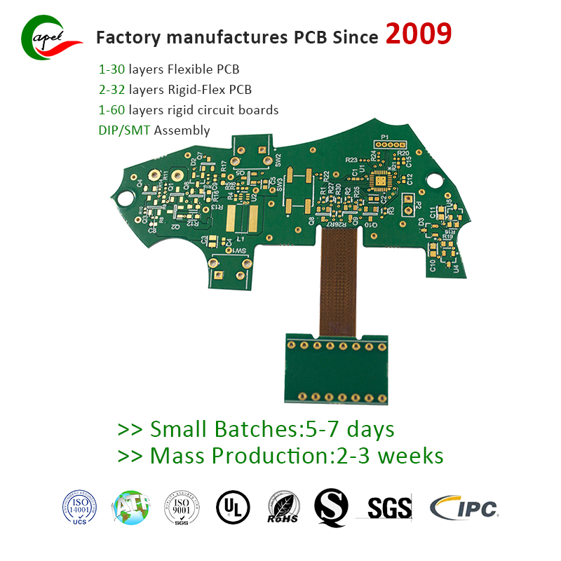
Kaboer manufacturing PCBs since 2009. Professional technology and high-precision Printed Circuit Boards involved in Medical, IOT, UAV, Aviation, Automotive, Aerospace, Industrial Control, Artificial Intelligence, Consumer Electronics etc..


 English


 Wechat
 +86 13670210335
 +86 13670210335
 E-mail